GROUP 3.5 - B SERIES
1 /25Pages

GROUP 3.5 - B SERIES
1 /25Pages
Catalog excerpts

GEAR PUMPS AND MOTORS "B" SERIES Technical catalogue
Open the catalog to page 1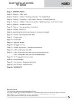
GEAR PUMPS AND MOTORS "B" SERIES Page 1 - GENERAL INDEX Page 2 - Features - Quick guide Page 3 - Features - General - Working conditions - Fire resistent fluid Page 4 - Features - Drive shaft - Pump rotation direction - Hydraulic pipe lines Page 5 - Features - Filtration index recommended - Tightening torque - Common formulas Page 6 - Features - Identification label Page 7 - Features - Changing rotation instructions Page 8 - 3.5P/MC GROUP 3.5 Page 9 - Assembling dimensions and values of pressure and speed Page 10 - Version interchangeable with 4PB Page 11 - Flanged ports Page 12 - Drive shafts...
Open the catalog to page 2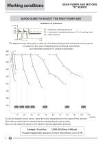
Working conditions GEAR PUMPS AND MOTORS "B" SERIES QUICK GUIDE TO SELECT THE RIGHT PUMP SIZE Definition of pressures P1 = Continuos operating pressure P2 = Intermittent operating pressure (1/3 of working time) P3 = Peak pressure max. 20 s The diagram shown here below is used as a first dimensioning aid for the choice of pump group. It is based on the value of displacements (horizontal coordinates) and intermittent pressure P2 (vertical coordinates) 5.5 3.2 1.4 2.8 2.6 5.8 To use the diagram shown above, select the pump displacement on the basis of flow required. Then draw a vertical line to...
Open the catalog to page 3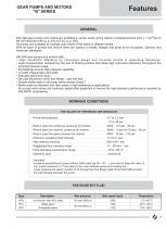
GEAR PUMPS AND MOTORS SALAMI gear pumps and motors are available in seven series giving options of displacements from 1.1 cm /rev to All pumps are available as multiple units either of the same or different series. With all sizes of pumps and motors there are options of shafts, flanges and ports as for European, German and American standards. SALAMI gear pumps and motors offer: • High volumetric efficiency by innovative design and accurate control of machining tolerances. • Axial compensation achieved by the use of floating bushes that allow high volumetric efficiency throughout the working pressure...
Open the catalog to page 4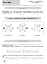
GEAR PUMPS AND MOTORS "B" SERIES Features DRIVE SHAFT Radial and axial loads on the shafts must be avoided since they reduce the life of the unit. Pumps driven by power take - off on engines must always be connected by placing an "Oldham" coupling or coupling having convex toothed hub. This is to ensure that inevitable misalignment during assembly is reduced to minimum. PUMP ROTATION DIRECTION VIEWED AT THE DRIVE SHAFT Anti - clockwise rotation Clockwise rotation Reversible rotation HYDRAULIC PIPE LINE To ensure favorable suction conditions it is important to keep pressure drop in suction pipe...
Open the catalog to page 5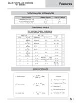
GEAR PUMPS AND MOTORS "B" SERIES FILTRATION INDEX RECOMMENDED Working pressure Achieved with filter ßx =75 TIGHTENING TORQUE PUMP TYPE BOLT TYPE FOR SCREWS ZINC PLATED REDUCE TIGHTENING TORQUE OF 10% OUR BOLTS AND TIE-RODS HAVE ALWAYS HEATING TREATMENT OF BLACK BURNISHING COMMON FORMULAS LEGENDA Dp = Working pressure (bar) q = Displacement (cm3/rev)
Open the catalog to page 6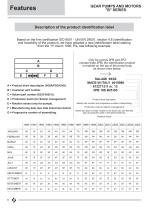
GEAR PUMPS AND MOTORS "B" SERIES Description of the product identification label Based on the firm certification ISO 9001 - UNI EN 29001, section 4.8 (identification and tracebility of the product), we have adopted a new identification label starting from the 1st march 1995. Pls, see following example: Only for pumps 2PB and 2PZ (except triple 2PB) the identification product is marked on the top of the pump body as shown here below: A = Product short descritpion (VD8A/FDD/U4G). B = Customer part number. C = Salami part number (6235 0025 0). D = Production batch (for Salami management) Product...
Open the catalog to page 7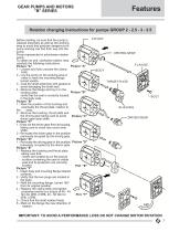
GEAR PUMPS AND MOTORS "B" SERIES Rotation changing instructions for pumps GROUP 2 - 2.5 - 3 - 3.5 Before starting, be sure that the pump is cleaned externally as well as the working area to avoid that particles dangerous for pump working can find their way into the pump. Pump represented is aclockwise rotation pump. To obtain an anti_clockwise rotation read carefully the following instructions. Picture "A" Picture "A" 1 - Loosen and fully unscrew the clamp bolts. 2 - Lay the pump on the working area in order to have the mounting flange turned upside. 3 - Coat the shaft extension with grease to...
Open the catalog to page 8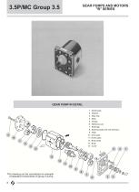
GEAR PUMPS AND MOTORS "B" SERIES GEAR PUMP IN DETAIL 1 - Shaft seals 2 - Washer 3 - Stop ring 4 - Bolts 5 - Flange 6 - Reference pin 7 - Bushings 8 - Bushing seals and anti-extrusion 9 - Plate 10 - Drive gear 11 - Driven gear 12 - Body seals 13 - Body 14 - Cover This drawing can be considered an example of standard components of group 3 pump. 8
Open the catalog to page 9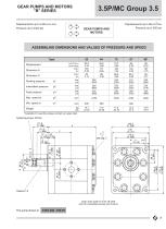
GEAR PUMPS AND MOTORS "B" SERIES Displacements up to 5.98 cu.in./rev Pressure up to 4300 psi GEAR PUMPS AND MOTORS ASSEMBLING DIMENSIONS AND VALUES OF PRESSURE AND SPEED Type Displacement Dimension A Dimension C Working pressure Intermittent pressure Peak pressure *Available for quantity, please contact our sales dept. Drain hole G3/8 or 9/16-18 UNF only for reversible pumps and motors
Open the catalog to page 10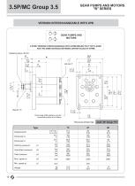
GEAR PUMPS AND MOTORS "B" SERIES VERSION INTERCHANGEABLE WITH 4PB GEAR PUMPS AND MOTORS 3.5P/MC VERSION INTERCHANGEABLE WITH 4P/MB MEANS THAT THE FLANGE HAS THE SAME DISTANCE BETWEEN CENTER HOLES OF 4P/MB Tightening torque 140 Nm Tapered 1:8 Drain hole G3/8 position only for reversible pumps and motors The pump shown has: shaft "49" flange "P4" Type Displacement Dimension A Dimension C Working pressure Intermittent pressure Peak pressure
Open the catalog to page 11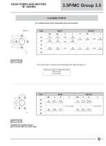
GEAR PUMPS AND MOTORS "B" SERIES FLANGED PORTS For unidirectional motor inlet/outlet ports are reversed. code P *For version 49 P4 (version interchangeable with 4PB see page 10) Tightening torque for different threads: M10: 50 Nm M12: 90 Nm code S Available for quantity, please get in touch with our sales dept.
Open the catalog to page 12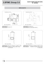
GEAR PUMPS AND MOTORS "B" SERIES 3.5P/MC Group 3.5 DRIVE SHAFTS SAE B 13T-16/32DP - Ansi B92 1a 1976 Available for quantity, please contact our sales dept. Tapered 1:8 Only with flange code P4 SAE BB 15T-16/32DP-Ansi B92 1a 1976 Available for quantity, please contact our sales dept.
Open the catalog to page 13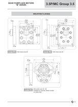
GEAR PUMPS AND MOTORS "B" SERIES MOUNTING FLANGES With shaft code 48 With shaft code 49 With shaft code 55 - 56 Available for quantity, please contact our sales dept.
Open the catalog to page 14All SALAMI catalogs and technical brochures
 2PE
2PE42 Pages
 3.5PC_Technical Catalogue
26 Pages
 2PGE_Technical Catalogue
34 Pages
 2ME_Technical Catalogue
28 Pages
 2.5MB_Technical Catalogue
24 Pages
 1.5ME_Technical Catalogue
20 Pages
 3PE and 3ME
53 Pages
 1,5PE
1,5PE41 Pages
 VDP08 and JOYSTICK oem and dealers
116 Pages
 VD10A - VD12A
32 Pages
 GROUP 2.5 - B SERIES
29 Pages
 GROUP 2 - E SERIES
35 Pages
 E series
15 Pages
 PG330
PG33034 Pages
 PLC series
11 Pages
 VDP08
VDP0846 Pages
 VDP8
VDP842 Pages
 VDM8 series
38 Pages
 VDM9
VDM922 Pages
 VDM6A series
35 Pages
 VDM6
VDM638 Pages
 VD8A series
48 Pages
 VD6A series
56 Pages
 PG301 series
13 Pages
 H series
33 Pages
 E series
13 Pages
 E series
26 Pages
 B series
32 Pages
 E series
20 Pages
Archived catalogs
 Product range
2 Pages
- Directional control valve
- Hydraulic pump
- Hydraulic directional control valve
- Spool hydraulic directional control valve
- Hydraulic motor
- Hydraulic gear pump
- Electrically-operated hydraulic directional control valve
- Manual hydraulic directional control valve
- Compact hydraulic pump
- High-pressure hydraulic pump
- Low-noise hydraulic pump
- Aluminum hydraulic pump
- Lever-operated hydraulic directional control valve
- Electro-hydraulic hydraulic directional control valve
- Monobloc hydraulic directional control valve
- Flow divider
- Cast iron hydraulic pump
- Gear hydraulic motor
- Hydraulic flow divider
- CAN Bus joystick