2PGE_Technical Catalogue
1 /34Pages

2PGE_Technical Catalogue
1 /34Pages
Catalog excerpts
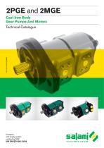
Cast Iron Body Gear Pumps And Motors Technical Catalogue with quality system
Open the catalog to page 1
GEAR PUMPS AND MOTORS “GE” SERIES Cast Iron Body GENERAL INDEX ▪ Feature Gear Pumps ▪ General features ▪ Technical data ▪ Definition of pressure ▪ Feature Gear Motors ▪ General features ▪ Technical data ▪ Definition of pressure ▪ Hydraulic pipe line ▪ Filtration index recommended ▪ Fire resistent fluid ▪ Common formulas for pumps and motors ▪ Combination with types of flanges and drives shafts ▪ Working conditions gear pumps ▪ Assembling dimensions ▪ Working conditions gear motors ▪ Assembling examples ▪ Mounting flanges with outrigger bearing support ▪ Drive shaft ▪ Pumps and motors rotation...
Open the catalog to page 2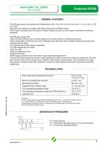
GEAR PUMPS “GE” SERIES Cast Iron Body GENERAL FEATURES SALAMI gear pumps are available with displacements from 16 cm3/rev to 26 cm3/rev (from 1.01 cu.in./rev to 1.58 cu.in./rev). All pumps are available as multiple units either of the same or different series. With all sizes of pumps there are options of shafts, flanges and ports as for European, German and American standards. SALAMI gear pumps offer: •High volumetric efficiency by innovative design and accurate control of machining tolerances. •Axial compensation achieved by the use of floating bushes that allow high volumetric efficiency throughout...
Open the catalog to page 4
GEAR MOTORS “GE” SERIES Cast Iron Body GENERAL FEATURES •Displacements from 16 cm3/rev to 26 cm3/rev (from 1.01 cu.in./rev to 1.58 cu.in./rev). •Rated pressure up to 250 bar (3625psi). •Back pressure capability up tp 120 bar (1740 psi) only in bi-directional release. •Speed up to 3200 rpm. •Flanges, shafts and ports for ISO, DIN and SAE standards. •Available in uni and bi-directional version for all the frame sizes, displacements and configurations. •High volumetric efficiency by innovative design and accurate control of machining tolerances. •Axial compensation achieved by the use of floating...
Open the catalog to page 5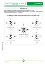
GEAR PUMPS AND MOTORS “GE” SERIES Cast Iron Body DRIVE SHAFTS Radial and axial loads on the shafts must be avoided since they reduce the life of the unit. In order to avoid misalignment during the assembly with the primary engine, a connection with “Oldham” coupling (or coupling having convex toothed hub) is recommended. PUMP AND MOTOR ROTATION DIRECTION VIEWED AT THE DRIVE SHAFT Anti - clockwise rotation PUMP Clockwise rotation PUMP Reversible rotation PUMP/MOTOR Outlet Anti - clockwise rotation MOTOR Clockwise rotation MOTOR
Open the catalog to page 6
HYDRAULIC PIPE LINE To ensure favorable suction conditions it is important to keep pressure drop in suction pipe line to a minimum value To calculate hydraulic pipe line size, the designer can use; as an approximate guide, the following fluid speed figures: From 1 to 2 m/sec on suction pipe line From to on suction pipe line From 6 to 10 m/sec on pressure pipe line From to on pressure pipe line The lowest fluid speed values in pipe lines is recommended when the operating temperature range is high and/or for continuos duty. The highest value is recommended when the temperature difference is low...
Open the catalog to page 7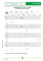
COMBINATION WITH TYPES OF FLANGES AND DRIVES SHAFTS AVAILABLE A/ofe; ofAier versions available, see shafts and flanges information.
Open the catalog to page 8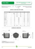
GEAR PUMPS AND MOTORS “GE” SERIES Cast Iron Body Displacements up to 1.58 cu.in./rev Pressure up to 4350 psi GEAR PUMPS Pdrain < 5 bar (43 psi) working conditions GEAR PUMPS Type Continuous pressure Intermittent pressure Peak pressure ASSEMBLING DIMENSIONS For flanges code: P1-B1-S2-S3, this dimension is 19 mm (0.75 in.) B4-B5-C1, this dimension is 16.5 mm (0.65 in.)
Open the catalog to page 9
GEAR PUMPS AND MOTORS “GE” SERIES Cast Iron Body Displacements up to 1.58 cu.in./rev Pressure up to 4000 psi GEAR MOTORS working conditions GEAR MOTORS Group 2 Type max. continuous pressure P1 max. starting pressure P2 Pin Motor outlet pressure Pout Leakage-oil line pressure Pdrain ASSEMBLING EXAMPLES
Open the catalog to page 10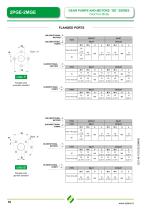
GEAR PUMPS AND MOTORS “GE” SERIES Cast Iron Body FLANGED PORTS UNI-DIRECTIONAL MOTORS UNI-DIRECTIONAL PUMPS code P Flanged ports european standard BI-DIRECTIONAL PUMPS UNI-DIRECTIONAL PUMPS OUTLET INLET BI-DIRECTIONAL MOTORS UNI-DIRECTIONAL MOTORS Flanged ports german standard BI-DIRECTIONAL PUMPS
Open the catalog to page 11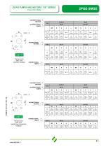
GEAR PUMPS AND MOTORS “GE” SERIES Cast Iron Body UNI-DIRECTIONAL MOTORS UNI-DIRECTIONAL PUMPS BI-DIRECTIONAL MOTORS Flanged ports SAE J518 METRIC THREAD BI-DIRECTIONAL PUMPS UNI-DIRECTIONAL MOTORS UNI-DIRECTIONAL PUMPS BI-DIRECTIONAL MOTORS code S Flanged ports SAE J518 AMERICAN STANDARD THREAD BI-DIRECTIONAL PUMPS
Open the catalog to page 12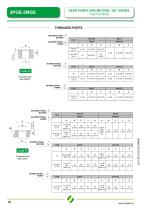
GEAR PUMPS AND MOTORS “GE” SERIES Cast Iron Body THREADED PORTS UNI-DIRECTIONAL MOTORS UNI-DIRECTIONAL PUMPS code G Threaded ports GAS (BSPP) BI-DIRECTIONAL PUMPS UNI-DIRECTIONAL MOTORS UNI-DIRECTIONAL PUMPS BI-DIRECTIONAL MOTORS code R Threaded ports SAE (ODT) BI-DIRECTIONAL PUMPS
Open the catalog to page 13
GEAR PUMPS AND MOTORS “GE” SERIES Cast Iron Body MOUNTING FLANGES European standard mounting flange With shaft code 28-62-81-82-85 German standard mounting flange With shaft code 25-62 German standard mounting flange With shaft code 25-62 German standard mounting flange With shaft code 25-62
Open the catalog to page 15
GEAR PUMPS AND MOTORS “GE” SERIES Cast Iron Body SAE A mounting flange With shaft code 52-54-82-85 SAE B mounting flange With shaft code 52-54-82-85 AVAILABLE FROM OCTOBER 2016 For Iveco engines mounting flange With shaft code 62 3 BOLT UNI 8953 mounting flange
Open the catalog to page 16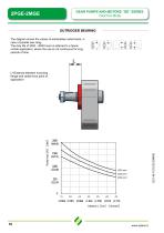
GEAR PUMPS AND MOTORS “GE” SERIES Cast Iron Body OUTRIGGER BEARING The diagram shows the values of admissibles radial loads, in case of parallel axis drag. The duty life of 3500 - 4000 hours is referred to a tipical mobile application, where the use is not continuous for long periods of time. L=Distance between mounting flange and radial force point of application
Open the catalog to page 17
GEAR PUMPS AND MOTORS “GE” SERIES Cast Iron Body MOUNTING FLANGES WITH OUTRIGGER BEARING SUPPORT European standard mounting flange With shaft code 25, 26 With shaft code 28 German standard mounting flange For engine endo thermic motors mounting flange SAE A mounting flange With shaft code 52-54-82-85 With shaft code 25-26 E0.146.1015.02.00IM00 AVAILABLE FROM OCTOBER 2016 AVAILABLE FROM OCTOBER 2016
Open the catalog to page 18All SALAMI catalogs and technical brochures
 2PE
2PE42 Pages
 3.5PC_Technical Catalogue
26 Pages
 2ME_Technical Catalogue
28 Pages
 2.5MB_Technical Catalogue
24 Pages
 1.5ME_Technical Catalogue
20 Pages
 3PE and 3ME
53 Pages
 1,5PE
1,5PE41 Pages
 VDP08 and JOYSTICK oem and dealers
116 Pages
 VD10A - VD12A
32 Pages
 GROUP 3.5 - B SERIES
25 Pages
 GROUP 2.5 - B SERIES
29 Pages
 GROUP 2 - E SERIES
35 Pages
 E series
15 Pages
 PG330
PG33034 Pages
 PLC series
11 Pages
 VDP08
VDP0846 Pages
 VDP8
VDP842 Pages
 VDM8 series
38 Pages
 VDM9
VDM922 Pages
 VDM6A series
35 Pages
 VDM6
VDM638 Pages
 VD8A series
48 Pages
 VD6A series
56 Pages
 PG301 series
13 Pages
 H series
33 Pages
 E series
13 Pages
 E series
26 Pages
 B series
32 Pages
 E series
20 Pages
Archived catalogs
 Product range
2 Pages
- Directional control valve
- Hydraulic pump
- Hydraulic directional control valve
- Spool hydraulic directional control valve
- Hydraulic motor
- Hydraulic gear pump
- Electrically-operated hydraulic directional control valve
- Manual hydraulic directional control valve
- Compact hydraulic pump
- High-pressure hydraulic pump
- Low-noise hydraulic pump
- Aluminum hydraulic pump
- Lever-operated hydraulic directional control valve
- Electro-hydraulic hydraulic directional control valve
- Monobloc hydraulic directional control valve
- Flow divider
- Cast iron hydraulic pump
- Gear hydraulic motor
- Hydraulic flow divider
- CAN Bus joystick