2PE
1 /42Pages

2PE
1 /42Pages
Catalog excerpts

Aluminium gear pumps Technical Catalogue
Open the catalog to page 1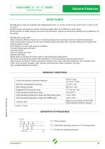
GEAR PUMPS “E”- “B”- “C” SERIES Aluminium Body General Features GEAR PUMPS SALAMI gear pumps are available with displacements from 1.4 cm3/rev to 99 cm3/rev (from 0.09 cu.in/rev to 6.03 cu.in/rev). Multiple pumps can always be relized combining stages taken from different or same series. Several options of shafts, flanges and ports as for European, German and American standards are available for all the pumps. SALAMI gear pumps offer: •High volumetric efficiency thanks to an innovative design and an accurate control of machining tolerances. •Axial compensation achieved by the use of floating...
Open the catalog to page 3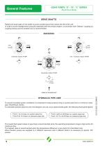
GEAR PUMPS “E”- “B”- “C” SERIES Aluminium Body General Features DRIVE SHAFTS Radial and axial loads on the shafts must be avoided since they reduce the life of the unit. In order to avoid misalignment during the assembly with the primary engine, a connection with “Oldham” coupling (or coupling having convex toothed hub) is recommended. Clockwise rotation PUMP Anti - clockwise rotation PUMP Reversible rotation PUMP HYDRAULIC PIPE LINE To ensure favorable suction conditions it is important to keep pressure drop in suction pipe line to a minimum value (see TECHNICAL DATA). To calculate hydraulic...
Open the catalog to page 4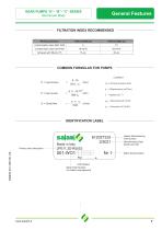
GEAR PUMPS “E”- “B”- “C” SERIES Aluminium Body General Features FILTRATION INDEX RECOMMENDED Working pressure Achieved with filter βx=75 COMMON FORMULAS FOR PUMPS IDENTIFICATION LABEL Product short description Salami Manufacturing Part Number Manufacturing Date, Month and Year Batch Serial Number Unit Rotation Build Order Number (for Salami management)
Open the catalog to page 5
GEAR PUMPS “E”- “B”- “C” SERIES Aluminium Body General Features TECHNICAL DATA Displacement GROUP 1.5 - E SERIES *Available only as rear pump cm3/rev *Available only as rear pump. Displacements 11.5-13.8 are available as single pump only with drive shaft “55”.
Open the catalog to page 6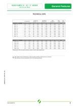
GEAR PUMPS “E”- “B”- “C” SERIES Aluminium Body General Features TECHNICAL DATA Displacement GROUP 3 - E SERIES *Displacement 98 are special release, please contact sales department. Max Speed must be lowered by 10% for system working continuosly at p1 pressure. Max pressure must be lowered by10% for bi-directional pump.
Open the catalog to page 7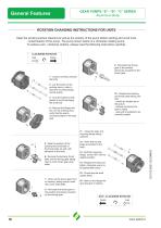
General Features GEAR PUMPS “E”- “B”- “C” SERIES Aluminium Body ROTATION CHANGING INSTRUCTIONS FOR UNITS Keep the working surface cleaned as well as the exterior of the pump before starting and avoid inner contamination of the pump. The pump shown below is a clockwise rotating pump. To achieve anti - clockwise rotation, please read the following instructions carefully. CLOCKWISE ROTATION Inlet Outlet 9 - Re-locate the driving gear in the position previously occupied by the driven gear. 1 - Loosen and fully unscrew the bolts. 2 - Lay the pump on the working area in order to have the mounting flange...
Open the catalog to page 8
GEAR PUMPS “E” SERIES Aluminium Body Final revised edition - February 2019 The data in this catalogue refers to the standard product. The policy of Salami S.p.A. consists of a continuous improvement of its products. It reserves the right to change the specifications of the different products whenever necessary and without giving prior information. If any doubts, please contact our sales department.
Open the catalog to page 9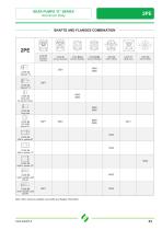
GEAR PUMPS “E” SERIES Aluminium Body SHAFTS AND FLANGES COMBINATION 2PE CODE P1 European Standard CODE B2-B3 German Standard CODE 04 Tang drive CODE 85 SAE A parallel shaft Ø19.05 CODE 82 SAE A parallel shaft Ø15.87 CODE C1 4 Bolts Iveco CODE 03 Tang drive for electric motors CODE B4-B5 German Standard CODE B1 German Standard Note: other versions available, see shafts and flanges information.
Open the catalog to page 11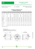
GEAR PUMPS “E” SERIES Aluminium Body 2PE Displacements up to 1.58 cu.in./rev Pressure up to 4350 psi GEAR PUMPS ASSEMBLING DIMENSIONS AND ASSEMBLING DIMENSIONS WORKING CONDITIONS Type Displacement Continuous pressure Intermittent pressure Peak pressure *Available only as rear pump For flanges code: P1-B1-S2-S6, this dimension is 19 mm (0.75 in.) B2-B3-B4-B5, this dimension is 16.5 mm (0.65 in.)
Open the catalog to page 12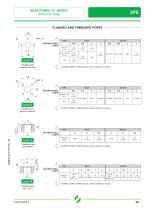
GEAR PUMPS “E” SERIES Aluminium Body FLANGED AND THREADED PORTS UNI-DIRECTIONAL PUMPS Flanged ports european standard BI-DIRECTIONAL PUMPS Special version available on request. Flanged ports german standard UNI-DIRECTIONAL PUMPS Threaded ports GAS (BSPP) BI-DIRECTIONAL PUMPS Special version available on request. UNI-DIRECTIONAL PUMPS BI-DIRECTIONAL PUMPS Special version available on request. UNI-DIRECTIONAL PUMPS
Open the catalog to page 13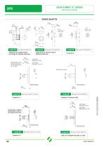
GEAR PUMPS “E” SERIES Aluminium Body DRIVE SHAFTS DRIVE SHAFTS Tang drive for engine driven For flange K1 without shaft seal Tang drive for electric motors Without shaft seal code 04 Tang drive Mounting face Mounting face Mounting face Mounting face
Open the catalog to page 14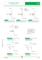
GEAR PUMPS “E” SERIES Aluminium Body Mounting face Mounting face Mounting face Mounting face DIN 5480 internal splined (only for rear pumps) Mounting face Mounting face
Open the catalog to page 15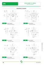
GEAR PUMPS “E” SERIES Aluminium Body MOUNTING FLANGES European standard With shaft code 28-62-82 German standard German standard With shaft code 25-62 German standard With shaft code 03 With shaft code 03 German standard With shaft code 25-62-04 German standard With shaft code 25-62-04
Open the catalog to page 16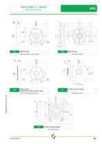
GEAR PUMPS “E” SERIES Aluminium Body SAE A 2 bolts With shaft code 52-53-54-82-85 SAE B 2 bolts With shaft code 55 SAE A 2 bolts (with O-ring on the centering collar) With shaft code 52-54-82-85 4 bolts for Iveco engines With shaft code 62 4 bolts for Perkins Motor With shaft code 02
Open the catalog to page 17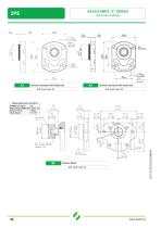
GEAR PUMPS “E” SERIES Aluminium Body German standard with shaft seal With shaft code 52 German standard with shaft seal With shaft code 52 Perkins Motor With shaft code 28
Open the catalog to page 18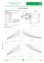
GEAR PUMPS “E” SERIES Aluminium Body OUTRIGGER BEARING The following diagrams show radial load capability of the bearing. Calculation according to ISO 281 at 10 cSt. TYPE L=Distance between mounting flange and radial force point of application. Expected life: 1000 hrs
Open the catalog to page 19All SALAMI catalogs and technical brochures
 3.5PC_Technical Catalogue
26 Pages
 2PGE_Technical Catalogue
34 Pages
 2ME_Technical Catalogue
28 Pages
 2.5MB_Technical Catalogue
24 Pages
 1.5ME_Technical Catalogue
20 Pages
 3PE and 3ME
53 Pages
 1,5PE
1,5PE41 Pages
 VDP08 and JOYSTICK oem and dealers
116 Pages
 VD10A - VD12A
32 Pages
 GROUP 3.5 - B SERIES
25 Pages
 GROUP 2.5 - B SERIES
29 Pages
 GROUP 2 - E SERIES
35 Pages
 E series
15 Pages
 PG330
PG33034 Pages
 PLC series
11 Pages
 VDP08
VDP0846 Pages
 VDP8
VDP842 Pages
 VDM8 series
38 Pages
 VDM9
VDM922 Pages
 VDM6A series
35 Pages
 VDM6
VDM638 Pages
 VD8A series
48 Pages
 VD6A series
56 Pages
 PG301 series
13 Pages
 H series
33 Pages
 E series
13 Pages
 E series
26 Pages
 B series
32 Pages
 E series
20 Pages
Archived catalogs
 Product range
2 Pages
- Directional control valve
- Hydraulic pump
- Hydraulic directional control valve
- Spool hydraulic directional control valve
- Hydraulic motor
- Hydraulic gear pump
- Electrically-operated hydraulic directional control valve
- Manual hydraulic directional control valve
- Compact hydraulic pump
- High-pressure hydraulic pump
- Low-noise hydraulic pump
- Aluminum hydraulic pump
- Lever-operated hydraulic directional control valve
- Electro-hydraulic hydraulic directional control valve
- Flow divider
- Monobloc hydraulic directional control valve
- Cast iron hydraulic pump
- Gear hydraulic motor
- Hydraulic flow divider
- High-pressure hydraulic motor