Catalog excerpts

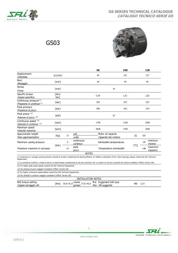
TS8 SERIES TECHNICAL CATALOGUE HYDRAULIC INPUT ^ MECHANICAL OUTPUT INPUT IDRAULICO OUTPUT MECCANICO POWER THROUGH EFFICIENCY
Open the catalog to page 1
TS8 SERIES TECHNICAL CATALOGUE CATALOGO TECNICO SERIE TS8 RADIAL LOAD CAPACITY CAPACITA’ DI CARICO RADIALE The permissible radial load curves are represented in the chart below for different values of bearing lifetime L10 (ref. ISO 281:1990). The L10 values are expressed in millions of revolutions, for a calculation of the equivalent working hours the following formula is requested: Nel grafico vengono rappresentate le curve limite di carico radiale considerando diversi valori di durata L10 (rif. ISO 281:1990) dei cuscinetti. I valori di L10 sono espressi in milioni di rivoluzioni, per...
Open the catalog to page 2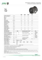
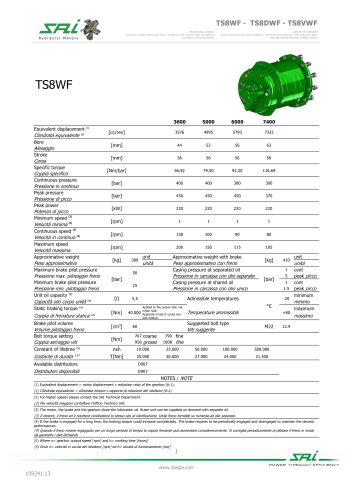
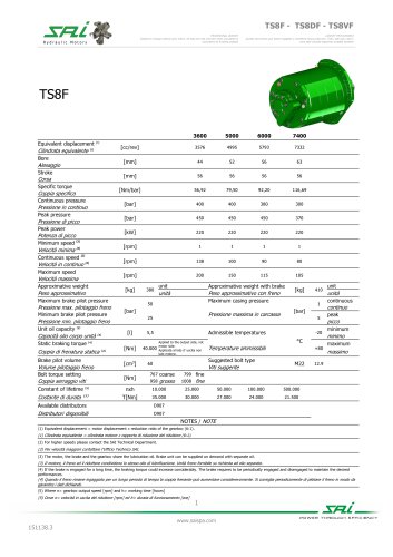
TS8 SERIES TECHNICAL CATALOGUE CATALOGO TECNICO SERIE TS8 Peak pressure Pressione di picco Peak power Potenza di picco Minimum speed Velocità minima Continuous pressure Specific torque Coppia specifica Equivalent displacement ⁽¹⁾ Cilindrata equivalente ⁽¹⁾ Bore Continuous speed Maximum speed Velocità massima Approximative weight Peso approssimativo Maximum brake pilot pressure Pressione max. pilotaggio freno Minimum brake pilot pressure Pressione min. pilotaggio freno Unit oil capacity ⁽³⁾ Capacità olio corpo unità ⁽³⁾ Static braking torque ⁽⁴⁾ Coppia di frenatura statica ⁽⁴⁾ Brake pilot...
Open the catalog to page 3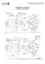
TS8 SERIES TECHNICAL CATALOGUE DIMENSIONAL DRAWINGS DISEGNI D'INGOMBRO POWER THROUGH EFFICIENCY
Open the catalog to page 4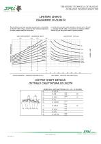
TS8 SERIES TECHNICAL CATALOGUE CATALOGO TECNICO SERIE TS8 LIFETIME CHARTS DIAGRAMMI DI DURATA Bearing lifetime has been estimated according to L10 (according to ISO 281:1990). Please contact the SAI Technical Department for other graphs related to this product. La durata dei cuscinetti è stata calcolata in accordo con la formula L10 (secondo ISO 281:1990). Vi preghiamo di contattare l’Ufficio Tecnico SAI per altri grafici relativi a questo prodotto. UNIT DISPLACEMENT - CILINDRATA UNITÀ 5000 PISTON DIAMETER - DIAMETRO PISTONE (Ø mm) UNIT SPEED - VELOCITÀ DELL’UNITÀ (rpm) OUTPUT SHAFT DETAILS...
Open the catalog to page 5
TS8 SERIES TECHNICAL CATALOGUE CATALOGO TECNICO SERIE TS8 (dual displacement without brake / cilindrata doppia senza freno) (variable displacement without brake / cilindrata variabile senza freno) (dual displacement with brake / cilindrata doppia con freno) (variable displacement with brake / cilindrata variabile con freno) Cilindrata equivalente (1) Bore Alesaggio Stroke Pressione in continuo Peak pressure Pressione di picco Peak power Continuous pressure Coppia specifica Specific torque Velocità in continuo (2) Maximum speed Velocità massima TD3.5 change displacement pilot pressure range...
Open the catalog to page 6
TS8 SERIES TECHNICAL CATALOGUE CATALOGO TECNICO SERIE TS8 NOTES / NOTE (1) Equivalent displacement = motor displacement x reduction ratio of the gearbox (6:1). (1) Cilindrata equivalente = cilindrata motore x rapporto di riduzione del riduttore (6:1). (2) For higher speeds please contact the SAI Technical Department. (2) Per velocità maggiori contattare l'Ufficio Technico SAI. (3) The motor, the brake and the gearbox share the lubricating oil. Brake unit can be supplied on demand with separate oil. (3) Il motore, il freno ed il riduttore condividono lo stesso olio di lubrificazione. Unità...
Open the catalog to page 7
TS8 SERIES TECHNICAL CATALOGUE CATALOGO TECNICO SERIE TS8 DIMENSIONAL DRAWINGS DISEGNI D'INGOMBRO Displ. pilot port axial position Displ. pilot port axial position POWER THROUGH EFFICIENCY
Open the catalog to page 8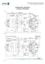
TS8 SERIES TECHNICAL CATALOGUE CATALOGO TECNICO SERIE TS8 DIMENSIONAL DRAWINGS DISEGNI D'INGOMBRO Gearbox brake axial position Gearbox brake POWER THROUGH EFFICIENCY
Open the catalog to page 9
TS8 SERIES TECHNICAL CATALOGUE CATALOGO TECNICO SERIE TS8 GRAPHS La durata dei cuscinetti è stata calcolata in accordo con la formula L10 (secondo ISO 281:1990). Il grafico che segue è stato ricavato usando le cilindrate massime e la corsa di 56 mm. Vi preghiamo di contattare l’Ufficio Tecnico SAI per altri grafici relativi a questo prodotto. Bearing lifetime has been estimated according to L10 (according to ISO 281:1990). The following graph refers to the maximum displacements having the stroke of 56 mm. Please contact the SAI Technical Department for other graphs relating to this product....
Open the catalog to page 10
TS8 SERIES TECHNICAL CATALOGUE CATALOGO TECNICO SERIE TS8 ORDER CODES high temperature seals clockwise rotation anti-clockwise rotation breath valve vedere tabella Posizione #1 (Standard) Position #1 (Standard) Direzione d'uscita (visto dal lato d'usci5 ta) con portata in ingresso in porta A, uscita in porta B. guarnizioni per alte temperature Nessun codice = rotazione oraria L rotazione antioraria Nessun codice = posizione 1 Orientamento 6 coperchio distributore Distributor cover orientation Direction of rotation (from the output side) with 5 input flow in port A, output in B.
Open the catalog to page 11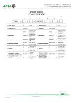
TS8 SERIES TECHNICAL CATALOGUE CATALOGO TECNICO SERIE TS8 ORDER CODES vedere tabella Hydraulic pilot Electrical pilot Electrical pilot Pilotaggio cilindra- Pilotaggio cilindra- Pilotaggio c/iindra- No code = slow change Nessun codice = cambio lento NS = no slow change NS = no cambio lento high tempera- ture seals breath valve alte temperature Direction of rotation NO code = rotation (viewed from the output side) with input flow in port A, out- Direzione d'uscita (visto dalla to d'usci- Nessun codice = rotazione oraria ingresso in porta A _ rotazi0ne anti- uscita in porta B. L - orana POWER...
Open the catalog to page 12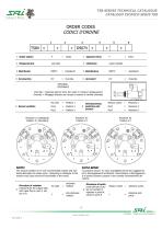
TS8 SERIES TECHNICAL CATALOGUE CATALOGO TECNICO SERIE TS8 ORDER CODES vedere tabella OPZIONALE Override = Hydraulic pilot to force the motor in minimum displacement. Override = Pilotaggio idraulico per forzare il motore in minima cilindrata. No code Posizione #1 (Standard) Position #1 (Standard) Orientamento/ posizione dei sensori NOTA BENE! The sensors’ position #2 is not recommended; shocks and accidental damages can easily occurr. tampering or damages to the sensors may cause incorrect functionality of the motor. Le posizioni sensori #2 sono sconsigliate perché più soggette ad urti e...
Open the catalog to page 13All SAI Motori Idraulici catalogs and technical brochures
-
Wheel catalogue
130 Pages
-
BD6A
5 Pages
-
TD3.5 TV3.5
6 Pages
-
TD1.5 TV1.5
6 Pages
-
BD1/BV1
7 Pages
-
GM1 R13
4 Pages
-
TF3.5
4 Pages
-
TF2.5
4 Pages
-
BD2 BV2 WR10
5 Pages
-
BD2 BV2 WR20
5 Pages
-
BD1 BV1 WR20
5 Pages
-
BD1 BV1 WR6B
5 Pages
-
BDK3A BDFK3A BVK3A BVFK3A
6 Pages
-
BDK3 BDFK3 BVK3 BVFK3
6 Pages
-
GK4 - GFK4
4 Pages
-
GK3A GFK3AR
5 Pages
-
GK3 GFK3R
5 Pages
-
BD1 BV1 F10L G3A
6 Pages
-
BD1 BV1 G3A
6 Pages
-
INTEGRATED SPEED SENSOR HU
2 Pages
-
FREEWHEELING BLOCK VALVE
2 Pages
-
F5S
2 Pages
-
BD6
4 Pages
-
BD3
4 Pages
-
BD2
10 Pages
-
P2G
2 Pages
-
TS8WF - TS8DWF - TS8VWF
11 Pages
-
TS8F - TS8DF - TS8VF
12 Pages
-
BD2 22B
4 Pages
-
BD2 F32
4 Pages
-
F21R - F21DR
3 Pages
-
F80S
5 Pages
-
GM2+F21E
5 Pages
-
GM5A R28
6 Pages
-
GM3A R24
5 Pages
-
GM2 R24
5 Pages
-
GM4 R23R
6 Pages
-
GM4 R22RFA
6 Pages
-
GM2 R07
6 Pages
-
TV3.5
6 Pages
-
TD3.5
6 Pages
-
TV2.5
6 Pages
-
TD2.5
6 Pages
-
TF1.5
4 Pages
-
TD1.5
6 Pages
-
GS6A
5 Pages
-
GS3
5 Pages
-
GS2
5 Pages
-
GS1
5 Pages
-
GS05
5 Pages
-
S7B
5 Pages
-
L9
4 Pages
-
GM5A
4 Pages
-
GM4
4 Pages
-
GM2
4 Pages
-
GM1
5 Pages
-
L7B
5 Pages
-
BDK4/ BDFK4
5 Pages
-
BDK3/BDFK3
6 Pages
-
BD1 BV1 WR10
5 Pages
-
BV1+G3
6 Pages
-
GM2/ GM3A R24
5 Pages
-
GM2 R20FA R21
3 Pages
-
P1G
2 Pages
-
GS5A
5 Pages
-
GS4
5 Pages
-
GM6
4 Pages
-
GM3
4 Pages
-
GM05
4 Pages
-
BD5
4 Pages
-
BD1
7 Pages
-
Cilindrata variable TV1.5
7 Pages
-
Cilindrata variable BV2
10 Pages
-
Cilindrata variable BV1
7 Pages
-
P2G 22/B
4 Pages
-
BV1 R13
6 Pages
-
P2G R09
4 Pages
-
GS03
5 Pages
-
DISTRIBUTORS
9 Pages
-
GM Series
63 Pages


