- Catalogs
- SAI Motori Idraulici
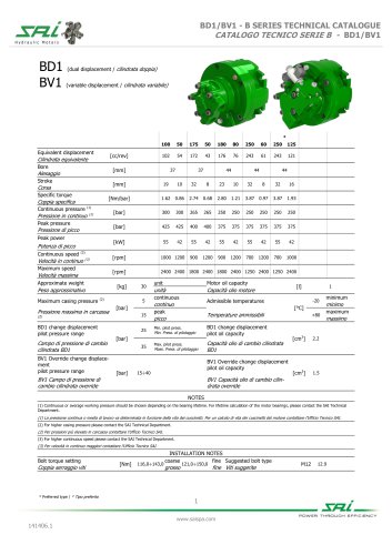
- BV1 R13
BV1 R13
1 /6Pages

BV1 R13
1 /6Pages
Catalog excerpts

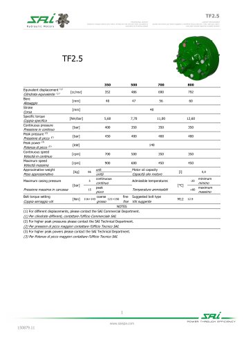
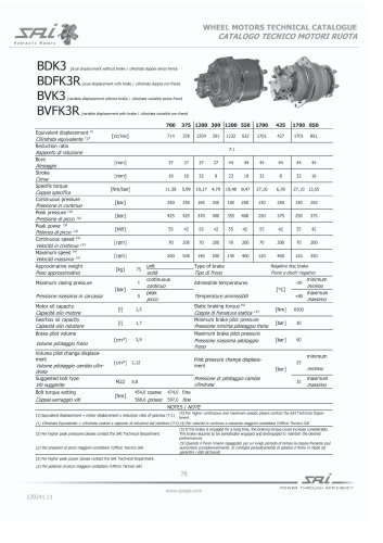
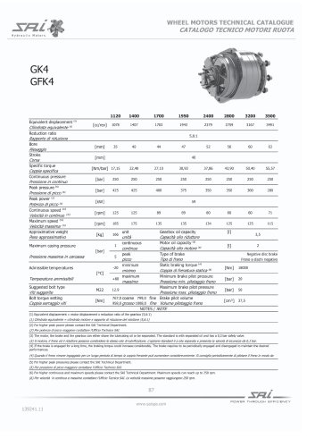
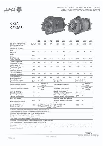
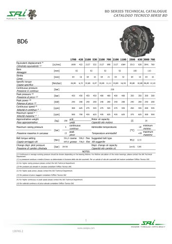
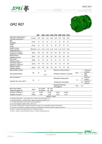
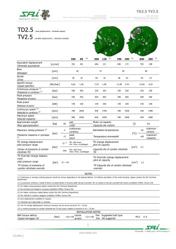
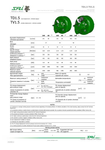
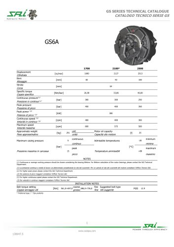
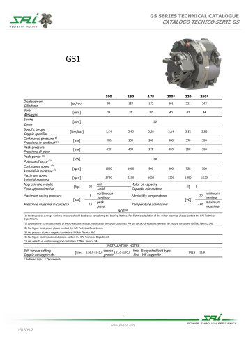
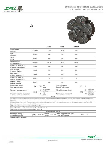
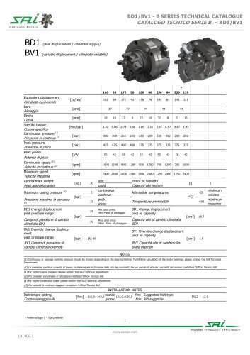
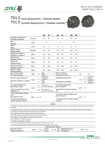
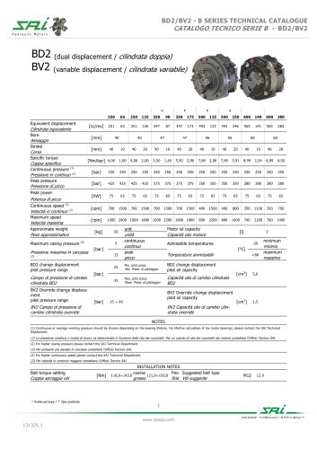
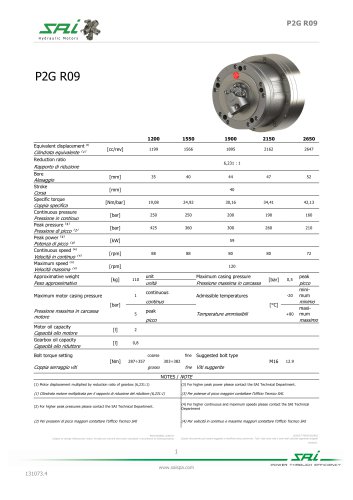
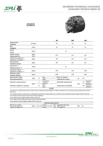
Reduction ratio Rapporto di riduzione Bore Alesaggio Stroke Corsa Specific torque Coppia specifica Continuous pressure Pressione in continuo Peak pressure ⁽²⁾ Pressione di picco ⁽²⁾ Peak power ⁽³⁾ Potenza di picco ⁽³⁾ Continuous speed ⁽⁴⁾ Velocità in continuo ⁽⁴⁾ Maximum speed ⁽⁴⁾ Velocità massima ⁽⁴⁾ Approx. weight Peso approssimativo Maximum casing pressure [bar] Pressione massima in carcassa Motor oil capacity Capacità olio motore Gearbox oil capacity Capacità olio riduttore Approx. weight with brake Peso approssimativo con freno Admissible temperatures Temperature ammissibili Coppia di frenatura statica ⁽⁵⁾ Pilot pressure change disp. 2,12 Minimum brake pilot pressure Bolt torque setting Coppia serraggio viti Press. minima pilotaggio freno Maximum brake pilot pressure Mass. press. pilotaggio freno 71,0 fine Suggested bolt type 89,0 fine Viti suggerite NOTES / NOTE Brake oil capacity Brake pilot volume Freno a dischi negativo Static braking torque ⁽⁵⁾ Press. pilotaggio cambio cil. Volume pilotaggio freno minimo maximum unità minimum Negative disc brake Volume pilotaggio cambio cil. Capacità olio freno Volume pilot change displ. [cm³] massimo minimum minimo maximum (1) Equivalent displacement = motor displacement x reduction ratio of gearbox (7:1) (3) For higher peak power please contact the SAI Technical Department. (1) Cilindrata Equivalente = cilindrata motore x rapporto di riduzione del riduttore (7:1) (3) Per potenze di picco maggiori contattare l'Ufficio Tecnico SAI. (2) For higher peak pressures please contact the SAI Technical Department. (4) For higher continuous and maximum speeds please contact the SAI Technical Department (2) Per pressioni di picco maggiori contattare l'Ufficio Tecnico SAI (4) Per velocità in continuo e massime maggiori contattare l'Ufficio Tecnico SAI LEAFLET PROVVISORIO Questo documento può essere soggetto a modifiche senza preavviso. Tutti i dati sono reali e sono stati calcolati seguendo progetti PROVISIONAL LEAFLET Subject to change without prior notice. All data are real and have been calculated in accordance to existing projects.
Open the catalog to page 1
DIMENSIONAL DRAWINGS DISEGNI D’INGOMBRO SHAFT OPTIONS SPLINE DATA OPZIONI ALBERO Standard shaft Standard shaft Albero standard Albero standard LEAFLET PROVVISORIO Questo documento può essere soggetto a modifiche senza preavviso. Tutti i dati sono reali e sono stati calcolati seguendo progetti PROVISIONAL LEAFLET Subject to change without prior notice. All data are real and have been calculated in accordance to existing projects.
Open the catalog to page 2
R13 WITH HYDRAULIC NEGATIVE DISCS BRAKE F10 hydraulic negative disc brake operating in oil bath can be fitted between motor and gearbox. The braking torque and the opening pressure of the brake depend on the number of disc thrust springs (see graph below). Max. pilot ressure 60 bar. II freno F10 e un freno distazionamento o emergenza, idraulico negativo a dischi multipli a bagno d'olio. La coppia frenante e la press/one di apertura del freno dipendono dal numero di molle spingi disco montate (vedi graficisotto). Pressione mass, dip/io- BRAKE TECHNICAL DATA / DATI TECNICI FRENO Nr. of springs...
Open the catalog to page 3
CHARACTERISTICS / CARATTERISTICHE Speed Velocità Pressure Pressione Flow LEAFLET PROVVISORIO Questo documento può essere soggetto a modifiche senza preavviso. Tutti i dati sono reali e sono stati calcolati seguendo progetti PROVISIONAL LEAFLET Subject to change without prior notice. All data are real and have been calculated in accordance to existing projects.
Open the catalog to page 4
PILOTS POSITION POSIZIONE PILOTAGGI Connector / Connettore: OverRide pilot port Porta dipilotaggio OverRide Connector / Connettore: PROVISIONAL LEAFLET LEAFLETPROWISORIO Subject to change without prior notice. All data are real and have been calculated in accordance to existing projects. Questo documento pud essere soggetto a modifiche senza preavviso. Tuttii datisono reali e sono stati calcolatiseguendo progetti POWER THROUGH EFFICIENCY
Open the catalog to page 5
ORDER CODES vedere tabella Without brake Unita senza freno clockwise rotation (viewed No code = from the output side) with flow in port A, out in port B. anti-clockwise rotation (viewed from the output side) with flow in port A, HU = Integrated speed sensor Nessun _ Rotazione oraria (visto fronte codice ~ albero) con input in porta A Rotazione anti-oraria (visto 3 Altre opzioni L = fronte albero) con input in HU = Sensore di velocita integrato I = 3 bar pressure relief valve SV = Anello speedy sleeve No code = Without brake Senza freno Esempio (standard) (options: FKM seals, anti-clockwise sense...
Open the catalog to page 6All SAI Motori Idraulici catalogs and technical brochures
 Wheel catalogue
130 Pages
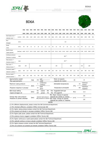 BD6A
BD6A5 Pages
 TD3.5 TV3.5
6 Pages
 TD1.5 TV1.5
6 Pages
 BD1/BV1
7 Pages
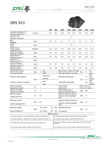 GM1 R13
4 Pages
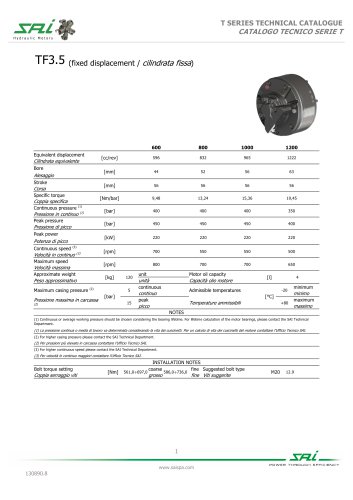 TF3.5
TF3.54 Pages
 TF2.5
TF2.54 Pages
 BD2 BV2 WR10
5 Pages
 BD2 BV2 WR20
5 Pages
 BD1 BV1 WR20
5 Pages
 BD1 BV1 WR6B
5 Pages
 BDK3A BDFK3A BVK3A BVFK3A
6 Pages
 BDK3 BDFK3 BVK3 BVFK3
6 Pages
 GK4 - GFK4
4 Pages
 GK3A GFK3AR
5 Pages
 GK3 GFK3R
5 Pages
 BD1 BV1 F10L G3A
6 Pages
 BD1 BV1 G3A
6 Pages
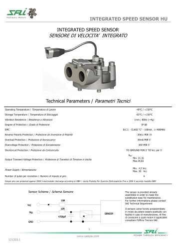 INTEGRATED SPEED SENSOR HU
2 Pages
 FREEWHEELING BLOCK VALVE
2 Pages
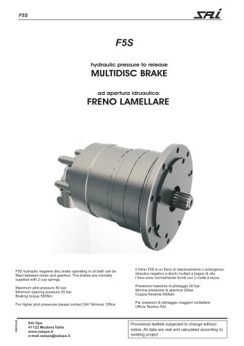 F5S
F5S2 Pages
 BD6
BD64 Pages
 BD3
BD34 Pages
 BD2
BD210 Pages
 P2G
P2G2 Pages
 TS8WF - TS8DWF - TS8VWF
11 Pages
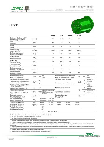 TS8F - TS8DF - TS8VF
12 Pages
 BD2 22B
4 Pages
 BD2 F32
4 Pages
 F21R - F21DR
3 Pages
 F80S
F80S5 Pages
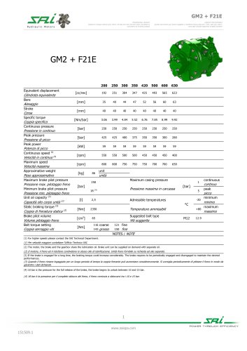 GM2+F21E
5 Pages
 GM5A R28
6 Pages
 GM3A R24
5 Pages
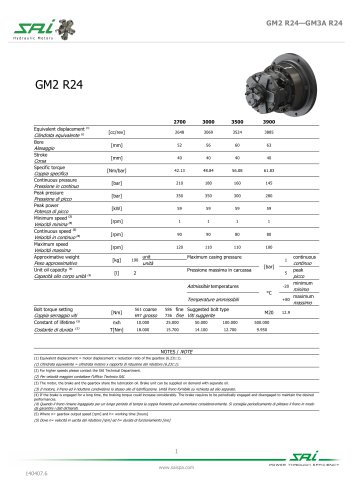 GM2 R24
5 Pages
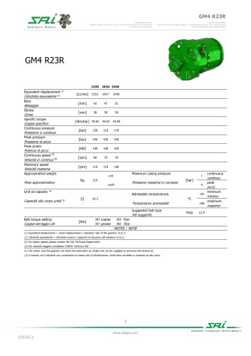 GM4 R23R
6 Pages
 GM4 R22RFA
6 Pages
 GM2 R07
6 Pages
 TV3.5
TV3.56 Pages
 TD3.5
TD3.56 Pages
 TV2.5
TV2.56 Pages
 TD2.5
TD2.56 Pages
 TF1.5
TF1.54 Pages
 TD1.5
TD1.56 Pages
 GS6A
GS6A5 Pages
 GS3
GS35 Pages
 GS2
GS25 Pages
 GS1
GS15 Pages
 GS05
GS055 Pages
 S7B
S7B5 Pages
 L9
L94 Pages
 GM5A
GM5A4 Pages
 GM4
GM44 Pages
 GM2
GM24 Pages
 GM1
GM15 Pages
 L7B
L7B5 Pages
 BDK4/ BDFK4
5 Pages
 BDK3/BDFK3
6 Pages
 BD1 BV1 WR10
5 Pages
 BV1+G3
6 Pages
 TS8
TS813 Pages
 GM2/ GM3A R24
5 Pages
 GM2 R20FA R21
3 Pages
 P1G
P1G2 Pages
 GS5A
GS5A5 Pages
 GS4
GS45 Pages
 GM6
GM64 Pages
 GM3
GM34 Pages
 GM05
GM054 Pages
 BD5
BD54 Pages
 BD1
BD17 Pages
 Cilindrata variable TV1.5
7 Pages
 Cilindrata variable BV2
10 Pages
 Cilindrata variable BV1
7 Pages
 P2G 22/B
4 Pages
 P2G R09
4 Pages
 GS03
GS035 Pages
 DISTRIBUTORS
9 Pages
 GM Series
63 Pages

- Friction brake
- Multi-channel manifold
- Hydraulic motor
- Hydraulic brake
- Piston hydraulic motor
- Emergency brake
- Fixed-displacement hydraulic motor
- Flow divider
- Radial piston hydraulic motor
- Compact hydraulic motor
- High-pressure hydraulic motor
- Variable-displacement hydraulic motor
- Valve manifold
- Hydraulic motor for heavy-duty applications
- Vacuum manifold
- Hydraulic wheel motor
- Gear hydraulic wheel motor
- Double-displacement hydraulic motor
- Compact hydraulic wheel motor