RSVC
1 /16Pages

RSVC
1 /16Pages
Catalog excerpts

RSVC VAV Circular Terminal Units
Open the catalog to page 1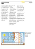
VAV Circular Terminal Units Comfort Variable Air Volume (VAV) HVAC systems are the best solution to guarantee high levels of comfort and energy efficiency in civil and industrial applications. VAV systems are well suited for the climate control of modern office buildings, with extensive glass facades and variable occupancy levels which cause uneven cooling loads profiles, with relevant values even in the winter season. For industrial process applications, such as research laboratories, the use of VAV systems allows to maintain the required differential pressure levels between adjacent rooms together...
Open the catalog to page 2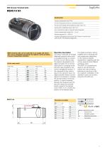
VAV Circular Terminal Units SagiCofim Construction Casing in galvanized steel Z 200 Air flow measurement device in extruded aluminium Air flow control blade with air tightness class 4 EN 1751 Casing with air tightness class C EN 1751 Duct connections male to male with silicone gaskets Control measurement range (0) 2...14 m/s Working pressure 30.1000 Pa Actuator with pressure sensor and VAV-Compact controller type LMV D3 MP F SG (linearized Sagicofim) RSVC terminal units can be used both on air supply and return. The correct installation guarantees the highest control precision. Pressure independent...
Open the catalog to page 3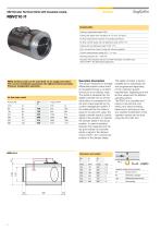
VAV Circular Terminal Units with insulated casing SagiCofim Construction Casing in galvanized steel Z 200 Casing with glass wool insulation tk. 50 mm, 30 kg/m3 Air flow measurement device in extruded aluminium Air flow control blade with air tightness class 4 EN 1751 Casing with air tightness class C EN 1751 Duct connections male to male with silicone gaskets Control measurement range (0) 2...14 m/s Working pressure 30.1000 Pa Actuator with pressure sensor and VAV-Compact controller type LMV D3 MP F SG (linearized Sagicofim) RSVC terminal units can be used both on air supply and return. The correct...
Open the catalog to page 4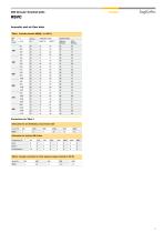
VAV Circular Terminal Units SagiCofim Acoustic and air flow data Table 1 Acoustic pressure (dB[A]) / Ap 100 Pa Attenuation for air distribution, low pressure side V in m3/h 500 1500 2500 4000 5000 6000 Attenuation for terminal dB / octave Frequency Hz 63 125 250 500 1000 2000 4000 8000 Table 2 Average correction for other pressure values referred to 300 Pa Ap in Pa 200 400 600 800 1000
Open the catalog to page 5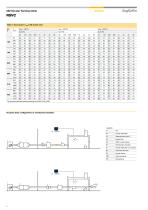
VAV Circular Terminal Units RSVC Table 3 Sound power / Lw The acoustic data are tested according to EN ISO 5135 : 2003 Acoustic data configuration in reverberant chamber
Open the catalog to page 6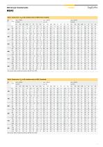
VAV Circular Terminal Units SagiCofim Table 4 Sound power / Lw The acoustic data are tested according to EN ISO 5135 : 2003 Table 5 Sound power / Lw The acoustic data are tested according to EN ISO 5135 : 2003
Open the catalog to page 7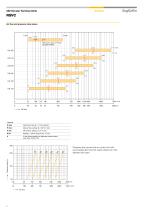
VAV Circular Terminal Units RSVC Air flow and pressure drop values Minimum value of Vmax, programmable Legenda V nom Nominal air flow (S x 14 m/s velocity) V max Max air flow, setting 40...100 % V nom V min Min air flow, setting &15 % V nom V int Setting 0...100 % range V min...V max 0 In the closing position air tightness values comply Pressure drop across the air control unit with sound attenuator and hot water reheat coil, with damper fully open.
Open the catalog to page 8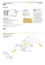
VAV Circular Terminal Units RSVC Electrical data Connections to safety transformer 1 LMV-D2-MP SG Technical data • Supply voltage 24 V AC / DC • Power consumption 2,5 W / 5 VA (max 5 A @ 5 ms) • Cable connection 1 m, 4 x 0,75 mm2 • Protection class III love voltage • Protection class IP54 • EMC CE according to 89/336 EEC Feedback signal U5 / MP-bus The U5 terminal provides a constant feedback of the actual air flow and is also the digital communication terminal with MP accessories. It is important to bring it on the control panel for operation data and functions re-programming. Notes for PP standard...
Open the catalog to page 9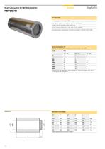
Sound attenuators for VAV Terminal Units RSVCS N1 Construction Casing in galvanized steel Z 200 Casing with glass wool insulation tk. 50 mm, 30 kg/m3 Casing with air tightness class C EN 1751 Duct connections female to male with silicone gaskets Acoustical test in reverberant chamber according to EN ISO 7535 : 2005 Pressure drop and regenerated noise values do not change with regards to air flow in circular ducts with the same DN * Direct airtight female connection to RSVC
Open the catalog to page 10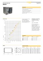
Hot water reheat coils RSVCH Construction Standard version 2 rows, copper / aluminium Casing in galvanized steel Duct connections with rubber gaskets Inspection door for tube cleaning Casing with air tightness class C EN 1751 Max 100 °C / 1 bar Technical data The graph applies under the following conditions: Atv = 20 °C in the water Inlet water temperature: 55 °C Inlet air temperature: 15 °C Calculation of water flow The water flow q (l/s) is calculated for the following formula: q (l/s) = P (W) / 82300 The formula assumes a temperature difference of 20 degrees in the water. The heat output P...
Open the catalog to page 11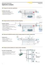
VAV Circular Terminal Units Application examples VAV - Compact for stand-alone applications Individual room comfort + • Wide range of potential applications • Adjustable to each application • Demand-based single-room application • Operation with Fan Optimiser Active / passive sensor Room temperature control panel VAV - Compact with bus connection and sensor integration Interface MP Intelligent simplicity • System connection to DDC controller with MP interface via MP-bus ® • Integration in higher-level systems such as LONWORKS ®, Konnex. Ethernet TCP/IP, Profibus DP, etc. via MP gateway • Convenient,...
Open the catalog to page 12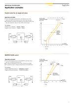
VAV Circular Terminal Units Application examples Parallel control for air supply and return Operation principle 1 The control signal is sent both to the Master and to the Slave controller which have the Vmin and Vmax set point. 2 The difference between the Master and the Slave air flow has the same absolute value on the whole control range. Air flow value measurement signal Es. 0...10V To maintain: positive room pressure = Supply > Return negative room pressure = Supply < Return Constant difference between supply and return Supply Room MASTER / SLAVE control Operation principle 1 The control signal...
Open the catalog to page 13All SagiCofim catalogs and technical brochures
 PV
PV2 Pages
 INDUL V45
3 Pages
 BPV - VENL0001
16 Pages
 DUG-B -DUG-A
2 Pages
 LBM - KBM
1 Page
 LLB - KK
1 Page
 AB - AA
3 Pages
 LS - KS
1 Page
 LMS - KMS - LNS - NS
1 Page
 DEC A -DEC S
3 Pages
 generale-Sale-Operatorie
8 Pages
 TAS.OP
8 Pages
 Pharmasafe
8 Pages
 AH - AS
1 Page
 CB-CA
CB-CA1 Page
 WHBLF - WBLF - KBLF
1 Page
 AH 710 - AH 780
1 Page
 AH 200 - AH 280
2 Pages
 AF 981 I
1 Page
 VEB-S - KK - KE
1 Page
 LT 151
2 Pages
 LT 500
3 Pages
 LT 350
3 Pages
 BE
BE2 Pages
 WS 230 P - WS 210 P
1 Page
 WS 400
1 Page
 WT
WT2 Pages
 EE 400
2 Pages
 CS 600 - CS 500
1 Page
 ZAR-R
ZAR-R1 Page
 AF 350
2 Pages
 AD 780
2 Pages
 AD 250 - GF 250
2 Pages
 DR 160
1 Page
 CV 100 - DE 100
3 Pages
 CAT-C
CAT-C1 Page
 SPIN-C
1 Page
 WR
WR2 Pages
 WR 400
1 Page
 TAB
TAB4 Pages
 ZAR-C
ZAR-C1 Page
 WT 500 S
1 Page
 CC 600
1 Page
 SDFZ
SDFZ1 Page
 DC 560 T
1 Page
 DC 560 S
1 Page
 DC 570 S
1 Page
 DC 570 T
1 Page
 SDFZ-R
1 Page
 LD 600
3 Pages
 KMF
KMF8 Pages
 KOMBI PVA 1 CC
2 Pages
 GP 100 - GP 50
2 Pages
 RSVC-K
4 Pages
 RSVB
RSVB16 Pages
 RSVQ
RSVQ12 Pages
 VRK
VRK1 Page
 VRRK
VRRK1 Page
 GTA 010 EN
12 Pages
 GT 019
12 Pages
 GT 018
12 Pages
 GT 050
12 Pages
 GT 015
12 Pages
 GTE 11
12 Pages
 GTE 05
12 Pages
 GTE 06
12 Pages
 GTE 10
12 Pages
 GTE 08
12 Pages
 GTA 010
12 Pages
 GTA 015
12 Pages
 SDL-SDLT
16 Pages
 HTE 400
14 Pages
 SFD-SFDT
16 Pages
 TB-TC
TB-TC1 Page
 AFO-AL1-AL2
3 Pages
 SA SA - LF
2 Pages
 MCA - MCPA
4 Pages
 RAS Applications
7 Pages
 RAS
RAS12 Pages
 INER-ST
8 Pages
 AD 300
2 Pages
 GS 130
1 Page
 GF 130
2 Pages
 GF / AF 500-530
2 Pages
 PDP
PDP1 Page
 MPS
MPS2 Pages
 PK
PK3 Pages
 JD
JD3 Pages
 FLG
FLG2 Pages
 INDULCLIP - INDUDRALL
2 Pages
 PFA/4/5
1 Page
 PFO/E/S/H
1 Page
 PFO/6/7/8/9
1 Page
 PFI-PFM-PFO/M
1 Page
 CARBO
CARBO1 Page
 CANISTER
4 Pages
 Multimod
1 Page
 CAB
CAB1 Page
 Modulo
1 Page
 CT
CT1 Page
 SAF
SAF1 Page
 CAB - PT
1 Page
 DAB - DAA
1 Page
 ABH - AAH
1 Page
 LLMB - KKMB
1 Page
- Filter with cartridge
- Filter cartridge
- Industrial use filter
- Industrial filter cartridge
- Fine filter cartridge
- Filter housing
- Dust separator filter
- Panel filter
- General purpose filter cartridge
- Flow controller
- Filter element
- Gas separator filter
- Metal filter housing
- Pneumatic flow regulator
- Air filter cartridge
- Pleated pre-filter
- Stainless steel filter housing
- Particulate pre-filter
- Aluminum pre-filter
- Bag filter