BPV - VENL0001
1 /16Pages

BPV - VENL0001
1 /16Pages
Catalog excerpts

BPV - VENL0001 Blast Protection Valves
Open the catalog to page 1
Blast Protection Valves Index page 1 SagiCofim Blast Protection Valve VENL0001 4 Functional tests at Spiez Laboratory with Air Blast Loading Shock Tube 6 2 Frame and fixing design criteria 7 Frame welded on counterframe 7 3.1 Dimensions of frames to be welded to counterframe 8 / 9 3.2 Dimensions of frames to be fixed with screw anchors 10 / 11 4 General constructive and installation features 12 4.1 Frames to be welded on embedded counterframe on metal structure 12 4.2 Frames to be fixed to wall with screw anchors 13 4.3 Frames to be...
Open the catalog to page 2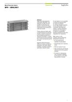
Blast Protection Valves Abstract SagiCofim blast protection valves BPV-VENL0001, are designed as safety devices capable of preventing any pressure wave due to sudden overpressure from entering air inlets and outlets. These valves are widely used in petrochemical and chemical industry, whenever temporary and immediate protection is required downstream a closed environment and the nominal air flow cannot be discontinued for too long. SagiCofim Blast Protection Valves can ensure an effective protection of all HVAC plants installed in buildings located in potentially explosive areas. In such plants...
Open the catalog to page 3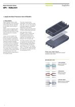
Blast Protection Valves 1. SagiCofim Blast Protection Valve VENL0001 1.1 Description Blast Protection Valves under code VENL0001 are mechanical self-actuated devices operated by the elastic forces acting on blades. Valves consist of stainless steel blade shutters installed within a modular die-cast aluminum alloy body, anodized for corrosion protection. Under normal conditions the device is at rest and its blades are fully released, positioned at the center of the valve body thus allowing the airflow passage. The blade shutters are designed to be tensioned and positioned into the valve seats by...
Open the catalog to page 4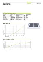
Blast Protection Valves 1.2 Technical details Blast valve general data - Model BPV-VENL0001 mm 400 x 181 x 100 Operation in both directions Pressure range Blast duration Airflow range Outstanding feature Body material Aluminum alloy Peak pressure downstream Blades material Stainless steel Closing time Temperature range Airflow rate per valve (m3/
Open the catalog to page 5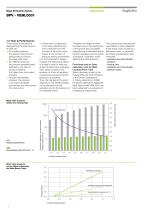
Blast Protection Valves Engineering SagiCofim 1.3 Tests & Performances The physical characteristics distinguishing the phenomenon of blast are: a) the incident pressure: the pressure the structure being protected (hence the valve) shall resist b) the reflected pressure: the pressure perpendicularly reflected by the valve in closing conditions. It is higher than the incident pressure c) the peak downstream pressure: the pressure occurring immediately downstream the valve during the closing time d) closing time: corresponds to the valve operating time and is reckoned from the moment of the...
Open the catalog to page 6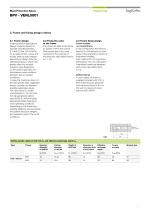
Blast Protection Valves 2.2 Fixing the valve to the frame The valves are fixed to the frame by means of M12 8.8 screws. Said screws are in any case oversized to the purpose of ensuring very high safety factors, (i.e. > 10). 2.1 Frame design In petrochemical applications, design incident pressure is typically included between 0.1 and 0.5 bar (10 / 50 KPa). As a matter of fact, valves and frames shall be sized instead assuming as design data the reflected pressure, which may greatly affect the incident pressure value depending on the system geometry, on the pressure wave incidence direction and...
Open the catalog to page 7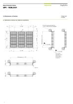
Blast Protection Valves ➀ Flanged type ➁ Flat type 3. Dimensions of frames 3.1 Dimensions of frames to be welded to counterframe Civil work must be embedded by L 100 x 10 UNI EU 56 (not supplied) n x 50 (100) Fixing detail: weld with seams 50 mm long at the distance of 100 mm
Open the catalog to page 8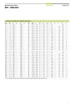
Blast Protection Valves 3.1 Dimensions of frames to be welded to counterframe C and D mesaurements are merely indicative and will be calculated according to project requirements
Open the catalog to page 9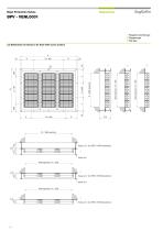
Blast Protection Valves ➀ Flanged & ducted type ➁ Flanged type ➂ Flat type 3.2 Dimensions of frames to be fixed with screw anchors Holes ø 12 for HTS / HTS-R anchors ➀ Holes ø 8 Wall opening = A - 260 Holes ø 12 for HTS / HTS-R anchors Holes ø 8 Holes ø 12 for HTS / HTS-R anchors
Open the catalog to page 10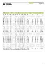
Blast Protection Valves 3.2 Dimensions of frames to be fixed with screw anchors C and D mesaurements are merely indicative and will be calculated according to project requirements
Open the catalog to page 11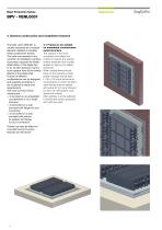
Blast Protection Valves The blast valve VENL001 is usually employed as a modular element installed on suitable metal containment frames. The valve can operate in any condition of installation (vertical, horizontal), because the elastic deformation of the blade due to an incident pressure wave is much greater than all the inertial effects of the blade itself. Frames of different configurations can be designed and supplied according to the Customer’s needs and requirements. The most common frame versions are: a) to be fixed on an embedded counterframe or on a metal structure b) to be bolted on...
Open the catalog to page 12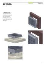
Blast Protection Valves 4.2 Frames to be fixed to wall with screw anchors This solution allows to fix the valves directly to the wall when the openings are not provided with metal counterframe. Our design is based on the conditon that the concrete wall is robust and smooth, therefore suitable to be coupled with the valve frames.
Open the catalog to page 13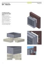
Blast Protection Valves 4.3 Frames to be fixed to wall with screw anchors and provided with a spacer plenum In case wall openings are available but their size is not compatible with the blast valves size, it is possible to employ specific frames which are provided with a spacer plenum allowing to couple different sections and permitting the air to flow. As far as sizing and fixing are concerned, the same criteria of the previous paragraph apply.
Open the catalog to page 14
Blast Protection Valves 5. Maintenance recommendations Since blast valve systems contain no moving details, they do not need any specific maintenance nor spare parts are required for their ordinary use and maintenance. We suggest to clean the valves periodically with clean water or compressed air, in order to remove any possible foreign body from them or from the shutter surface. If necessary, each single valve can be removed from its support frame unscrewing the 4 M12 bolts which fix each single valve. We strongly recommend not to disassemble the blast valves! If necessary, SagiCofim will provide...
Open the catalog to page 15All SagiCofim catalogs and technical brochures
 PV
PV2 Pages
 INDUL V45
3 Pages
 DUG-B -DUG-A
2 Pages
 LBM - KBM
1 Page
 LLB - KK
1 Page
 AB - AA
3 Pages
 LS - KS
1 Page
 LMS - KMS - LNS - NS
1 Page
 DEC A -DEC S
3 Pages
 generale-Sale-Operatorie
8 Pages
 TAS.OP
8 Pages
 Pharmasafe
8 Pages
 AH - AS
1 Page
 CB-CA
CB-CA1 Page
 WHBLF - WBLF - KBLF
1 Page
 AH 710 - AH 780
1 Page
 AH 200 - AH 280
2 Pages
 AF 981 I
1 Page
 VEB-S - KK - KE
1 Page
 LT 151
2 Pages
 LT 500
3 Pages
 LT 350
3 Pages
 BE
BE2 Pages
 WS 230 P - WS 210 P
1 Page
 WS 400
1 Page
 WT
WT2 Pages
 EE 400
2 Pages
 CS 600 - CS 500
1 Page
 ZAR-R
ZAR-R1 Page
 AF 350
2 Pages
 AD 780
2 Pages
 AD 250 - GF 250
2 Pages
 DR 160
1 Page
 CV 100 - DE 100
3 Pages
 CAT-C
CAT-C1 Page
 SPIN-C
1 Page
 WR
WR2 Pages
 WR 400
1 Page
 TAB
TAB4 Pages
 ZAR-C
ZAR-C1 Page
 WT 500 S
1 Page
 CC 600
1 Page
 SDFZ
SDFZ1 Page
 DC 560 T
1 Page
 DC 560 S
1 Page
 DC 570 S
1 Page
 DC 570 T
1 Page
 SDFZ-R
1 Page
 LD 600
3 Pages
 KMF
KMF8 Pages
 KOMBI PVA 1 CC
2 Pages
 GP 100 - GP 50
2 Pages
 RSVC-K
4 Pages
 RSVB
RSVB16 Pages
 RSVC
RSVC16 Pages
 RSVQ
RSVQ12 Pages
 VRK
VRK1 Page
 VRRK
VRRK1 Page
 GTA 010 EN
12 Pages
 GT 019
12 Pages
 GT 018
12 Pages
 GT 050
12 Pages
 GT 015
12 Pages
 GTE 11
12 Pages
 GTE 05
12 Pages
 GTE 06
12 Pages
 GTE 10
12 Pages
 GTE 08
12 Pages
 GTA 010
12 Pages
 GTA 015
12 Pages
 SDL-SDLT
16 Pages
 HTE 400
14 Pages
 SFD-SFDT
16 Pages
 TB-TC
TB-TC1 Page
 AFO-AL1-AL2
3 Pages
 SA SA - LF
2 Pages
 MCA - MCPA
4 Pages
 RAS Applications
7 Pages
 RAS
RAS12 Pages
 INER-ST
8 Pages
 AD 300
2 Pages
 GS 130
1 Page
 GF 130
2 Pages
 GF / AF 500-530
2 Pages
 PDP
PDP1 Page
 MPS
MPS2 Pages
 PK
PK3 Pages
 JD
JD3 Pages
 FLG
FLG2 Pages
 INDULCLIP - INDUDRALL
2 Pages
 PFA/4/5
1 Page
 PFO/E/S/H
1 Page
 PFO/6/7/8/9
1 Page
 PFI-PFM-PFO/M
1 Page
 CARBO
CARBO1 Page
 CANISTER
4 Pages
 Multimod
1 Page
 CAB
CAB1 Page
 Modulo
1 Page
 CT
CT1 Page
 SAF
SAF1 Page
 CAB - PT
1 Page
 DAB - DAA
1 Page
 ABH - AAH
1 Page
 LLMB - KKMB
1 Page
- Filter with cartridge
- Filter cartridge
- Industrial use filter
- Industrial filter cartridge
- Fine filter cartridge
- Filter housing
- Dust separator filter
- Panel filter
- General purpose filter cartridge
- Flow controller
- Filter element
- Gas separator filter
- Metal filter housing
- Pneumatic flow regulator
- Air filter cartridge
- Pleated pre-filter
- Stainless steel filter housing
- Particulate pre-filter
- Aluminum pre-filter
- Bag filter