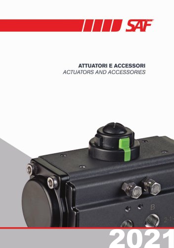
Overview: The document provides comprehensive technical specifications and descriptions of aluminium series rotary actuators, focusing on both double-acting and spring return types. It covers components, materials, technical data, and maintenance procedures.
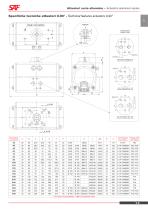
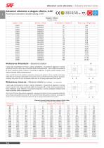
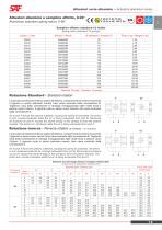
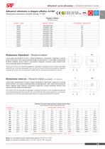
Technical Specifications: Actuators are available in various sizes with specific dimensions and pressure ratings. Tables detail output torque for different
actuator diameters and pressure levels for both double-acting and spring return models.
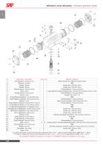
Components and Materials: Key components include position indicators, pinions, bodies, heads, pistons, adjustment screws, springs, bearings, guides, and O-rings. Materials range from nickel-plated steel and anodized aluminium to low friction materials for bearings and guides. High and low-temperature seals are available upon request.
Certifications and Standards: Actuators comply with SIL certification according to IEC 61508:2010 and the ATEX 2014/34/EU Directive, ensuring suitability for safety applications and hazardous environments.
Operation and Maintenance: Describes standard and reverse rotation operations, detailing how air pressure affects piston movement and pinion rotation. Maintenance guidelines emphasize ease of replacing components like springs and bearings to meet different torque requirements.
Key Features: Actuators are compact yet maintain high torque levels, featuring a multifunctional open-close indicator and adjustable settings. They meet demanding market requirements through robust design and compliance with international standards.
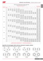
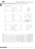
Specifications: Spring return actuators have a rotation range of 0-90°, suitable for safety applications, and comply with standards II 2G Ex h IIC T6 Gb and II 2D Ex h IIIC T85°C Db. Available in sizes with diameters from 52 mm to 400 mm and weights from 1.35 kg to 285 kg. Standard configuration includes 12 springs, with an option for 16 springs.
Performance Data: Detailed tables show output torque of spring return actuators at different pressures (2.5 to 8 bar) and actuator diameters, indicating performance under various operational conditions.
Technical Features: Part of the aluminium series, designed for both single and double acting operations, with a rotation range of 0-180°, highlighting constant output torque across this range.
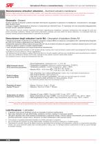
Installation and Maintenance: Emphasizes proper installation, operation, and maintenance. Advises against using actuators with flammable, oxidizing, corrosive, or explosive gases. Pre-lubricated and require no additional lubrication. Operating beyond specified limits can pose safety risks and damage the actuator.
Design and Construction: Features a rack and pinion design, suitable for quarter-turn
valve applications. Internal finish and low-friction materials ensure long-lasting performance without maintenance. Includes detailed dimensions and connection specifications for each actuator size.
Overview of Actuator System: Designed for 1/4 turn valves or applications, featuring a special interior surface finish and antifriction pads to prevent metal contact, ensuring a long, maintenance-free life.
Technical Specifications: Suitable for zones 1, 2, 21, 22 with a maximum surface temperature of T6 (85°C) and ambient temperature range of -20°C to +80°C. ATEX Mark: II 2G Ex h IIC T6 Gb, II 2D Ex h IIIC T85°C Db.
Operating Media: Clean, dry, or lubricated compressed air, light hydraulic oil, inert and non-corrosive gases with a maximum particle size of 30 μm.
Supply Pressure: Minimum 2 bar (~30 psi), Maximum 8 bar (~120 psi).
Operating Temperature: Standard (-20°C to +80°C), Low temperature (-40°C to +80°C), High temperature (-15°C to +150°C). Special grease is required for extreme temperatures.
Instructions for Use and Maintenance: Follow instructions to avoid warranty voidance. Ensure correct alignment and assembly of components.
Double Acting Actuators: Standard and reverse rotation instructions provided for air connections.
Spring Return Actuators: Instructions for standard and reverse rotation, emphasizing correct rotation direction for fail-safe operations.
Disassembly Instructions: Step-by-step guide for safely disassembling the actuator, including warnings and component checks.
Inspection and Maintenance: Recommended every 500,000 cycles, with a list of parts to inspect and replace.
Assembly Instructions: Detailed steps for reassembling the actuator, ensuring correct alignment and lubrication of components.
Key Components and Replacement Parts: A detailed list of components with descriptions and quantities, including recommended replacement parts for maintenance.
Specifications and Components: Details the RAX series pneumatic actuators, designed with a rack and pinion mechanism and a stainless steel AISI 316 body. Available in both double and single acting versions with return springs. Feature a multi-function open-close indicator and adjustable opening/closing. Highly resistant to aggressive environments and SIL certified according to IEC 61508:2010 and conform to the 2014/34/EU ATEX Directive.
Adjustment Procedures: Provides detailed instructions for adjusting the stroke of the actuators both clockwise and counterclockwise.
Pressure Testing: Actuators should be pressure tested with 6 bar compressed air. Leaks can be detected by spraying a soap and water solution on all joints and rotating shafts.
Storage Recommendations: Ensure actuators are dry, keep original protective plugs on air inlets, and protect from dust and damage by packing them in boxes or plastic bags.
Safety Warnings: Important safety warnings include ensuring pressure supply lines and electrical connections are isolated before maintenance, avoiding body contact with the valve, and not disassembling spring cartridges due to stored energy risks. Proper sizing and torque margin are crucial for correct operation.
Operation Time and Air Consumption: Includes tables detailing operation times for various actuator models in both double acting and spring return configurations. Provides air volume requirements for opening and closing operations.
Materials and Construction: Constructed with high-quality materials such as stainless steel and polyoxymethylene, ensuring resistance to corrosion and long life. Components include position indicators, pinions, bodies, heads, pistons, springs, bearings, and O-rings, with options for high and low-temperature seals available on request.
Technical Specifications: Provides detailed specifications for the Stainless Steel series actuators, including dimensions, weight, and pressure ratings. Designed for a temperature range of -40°C to +80°C, with specific O-ring materials required for different temperature conditions. Available in various sizes, each with specific torque outputs at different pressures.
Actuator Types: Two main types described: double acting and spring return. Double acting actuators use air pressure to move pistons in both directions, while spring return actuators use air pressure to compress springs, which then return the pistons to their original position when the air pressure is released.
Installation and Maintenance: Pre-lubricated and require no additional lubrication. Should not be used with flammable, oxidizing, corrosive, or explosive gases. Operating beyond specified limits can cause safety risks and damage. Emphasizes the importance of following installation instructions to avoid voiding the warranty.
ATEX Technical Parameters: Suitable for use in zones 1, 2, 21, and 22, with a maximum surface temperature of 85°C. Compatible with clean, dry, or lubricated compressed air, light hydraulic oil, and inert non-corrosive gases, with a maximum particle size of 40 μm.
Operating Conditions: Operate at a minimum pressure of 2 bar and a maximum of 8 bar. Special grease is required for low and high temperature applications, as these conditions affect the actuator's torque output.
Safety and Compliance: Designed for safety applications and comply with SIL standards. Proper training is required for assembly and disassembly to ensure safety and functionality.
Instructions for Use and Maintenance:
Double Acting Actuator: Describes the standard and reverse rotation mechanisms. In standard rotation, air to port A moves pistons outward, turning the pinion counterclockwise, while air is exhausted from port B. Reverse rotation involves air to port A moving pistons outward, turning the pinion clockwise.
Spring Acting Actuator: Similar mechanisms are described for spring acting actuators, with the addition of spring compression and release affecting pinion rotation.
Assembly Instructions: Actuators have a double square "star" pattern drive shaft and ISO standard mounting. Key steps include
fitting the valve square into the actuator, ensuring alignment, and securing with ISO pad bolts. Important considerations include determining valve operation (NC or NO) and ensuring correct alignment and position indicators.
Disassembly Instructions: Steps include safely disconnecting power, removing accessories, and disassembling the actuator. Caution is advised for spring return units to ensure they are in the failed position before disassembly. Components should be inspected for wear and replaced as necessary.
Inspection and Maintenance: Regular maintenance is recommended every 500,000 cycles. Key components for replacement include various O-rings, bearings, and washers.
Assembly of Actuator: Ensure all O-rings and gaskets are properly seated and greased. Steps include refitting the pinion, pistons, and end caps, with attention to correct alignment and avoiding pinching O-rings.
Endstop Adjustment: Instructions for adjusting the external stroke include loosening the security nut, adjusting the screw, and retightening the nut.
Pressure Test: Actuators should be tested at 6 bar compressed air, checking for leaks with a soap and water solution.
Storage Recommendations: Ensure actuators are dry, use protective plugs on air inlets, and protect from dust and damage by packing appropriately.
Important Safety Notices: Before maintenance or repair, ensure pressure and electrical connections are safely isolated and disconnected by authorized personnel.
Specifications: Provides detailed specifications for the RAE300 series electrical actuators, including power consumption of 3.5 W, weight of 5.2 kg, and protection grade IP67 according to IEC 60529. Operating temperature range is -20°C to +70°C (-4°F to +158°F). Electrical connections are compatible with DIN 43650 / ISO 4400 & C192 standards, and the interface follows ISO 5211, DIN 3337, and NAMUR standards. Actuators feature a position indicator ranging from 0° to 90°.
Electrical Consumption: A complete electrical consumption data sheet is available on page 1.38.
Optional Accessories: Optional accessories include a DPS digital positioner with various input options (4-20mA, 0-20mA, 0-10V, 1-10V), a BSR emergency fail-safe kit system by battery, a digital potentiometer (1K, 5K, 10K), and a three-position indicator (0°÷45°÷90°, 0°÷90°÷180°).
Electrical Actuators: The RAEH300 and RAEL300 models have a voltage range of 24 - 240 VAC and 24 - 110 VDC for RAEH300, and 12V AC or DC for RAEL300. Operation time is 48 seconds, with a breakaway torque of 350 Nm and an operating torque of 300 Nm. Working angle is 90° with optional 180° or 270°.
Maintenance and Safety: Recommended that only qualified electronic operators perform assembly and setting of the actuators. Ensure power is off before removing the cover. Each actuator should have an independent fuse system to protect against electrical induction from other equipment.
Instructions for Use and Maintenance: Emphasizes the importance of reading instructions before connecting the actuator, as non-compliance can void the warranty. Actuators are multi-voltage with automatic current sensing, and specific voltage ranges must be adhered to avoid damage.
Electrical Connections: Made using DIN plugs, with specific pin configurations for neutral and phase connections. Proper installation of rubber washers is crucial to prevent water infiltration.
Manual Operation: RAE actuators can be manually operated in case of power failure. The mode is selected via a lever, with options for automatic (AUTO) and manual (MAN) operation. Incorrect handling can void the warranty.
Visual Indicators: All RAE actuators come with a visual indicator for local position, showing both position and rotation direction.
LED Configuration and Actuator States: Describes the LED light configurations used to indicate the operational state of an actuator. Each configuration consists of a sequence of four numbers, where '1' indicates the LED is on and '0' indicates it is off. Various states such as 'Actuator without power', 'Actuator with power', and 'Actuator with torque limiter activated' are represented by specific LED sequences.
Mounting Instructions: Proper assembly of the mounting kit is crucial for aligning the actuator with its components, such as valves. The mounting holes must comply with ISO 5211 standards, and the female output must conform to DIN 3337. Non-compliance can lead to irregular friction and reduced lifespan of the actuator and valve.
Power Supply and BSR System: In the event of a power outage, the actuator will stop in its current position. If equipped with a BSR system, it will move to a preset safety position. Specifies the behavior for normally open (NO) and normally closed (NC) configurations.
Electrical Consumption Data: Provides detailed tables of electrical consumption for various actuator models (RAEL and RAEH series) across different voltages. Includes data on unload current and power, maximum operating torque, and maximum breakaway torque for different torque levels (20Nm, 35Nm, 55Nm, 85Nm, 140Nm, and 300Nm).
Maintenance Instructions: Maintenance should only be performed by authorized and skilled personnel to ensure safety and proper functioning of the actuators.






 Air Exhaust Mufflers
 Accesso for Cylinders
 Ancillary Valves
 Standard Fittings
 Rapid Fittings
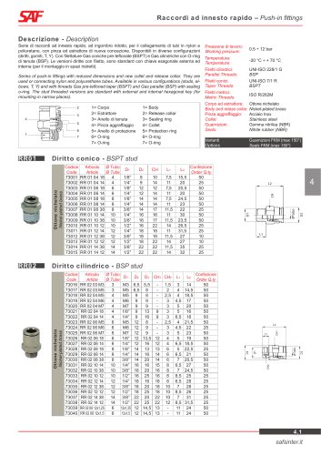 Push-in Fittings
 Filters
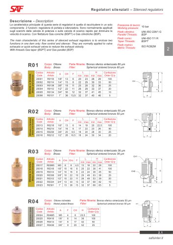 Silenced Regulators
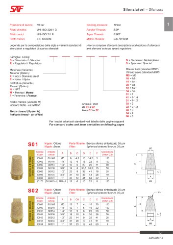 Silencers
 Aalve Assembly
 Accessories
 Spring Return Handles
 Handweel Gearbox
 Solenoid Valves
 Limit Switch Box
 Actuators Brochure
 Filters Brochure