Catalog excerpts

Electric Wrap Spring Clutch Technical Datasheet Radial Electric Wrap Spring Clutch Concept How it works As electric current is passed through the stationary coil, lines of magnetic flux are generated and used to Connector: Energizes clutch from outside source Stationary Coil: Generates magnetic flux when energized Magnetic Flux: Lines of magnetic flux cause the ring to engage Shoulder: Pressed on shaft for control ring attraction Shaft: Used as input or output as dictated by application. Driven by cross pin slot on opposite end Wrap Hub: Pressed on shaft for spring torque transfer attract the control ring to the shoulder. This control ring is attached to the spring, which wraps down onto a hub as the input is turned. Torque is transferred from the input, through the spring, to the output. After electric current is removed, the magnetic attraction is lost, causing the clutch to disengage as the spring unwraps. Floating Control Ring: Attracted to shoulder when magnetized Three Dog Hub: Used as input or output as dictated by application Spring: Fixed on three dog hub. During engagement spring wraps down on wrap hub to transfer torque Stationary Case: Encloses clutch components, protecting them from contamination How to Determine the Direction of Rotation Direction of rotation viewed from the input end of the clutch. Shaft Input
Open the catalog to page 1
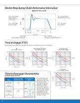
Electric Wrap Spring Clutch Performance Information Speed to Time Curve T.T.E. — Time-to-Engage: Time for magnetic flux buildup in clutch to activate the control ring and wrap spring. T.T.D. — Time-to-Disengage: Time for magnetic flux to decay and the spring to unwrap. T.T.S. — Time-to-Speed: T.T.E. + the time for the system to accelerate. T.T.Z. — Time-to-Zero: T.T.D. + deceleration time of the system. Torque is applied to output at T.T.E. Torque is removed from output at T.T.D. Time-to-Engage (T.T.E.) Time-to-Engage is directly related to the input speed. The higher the input speed, the...
Open the catalog to page 2
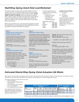
Reell Wrap Spring Clutch Total Load Worksheet The inertia about the axis of a cylinder is given by the formula: I= π/32 x D4 x L x ρ I=Inertia lb-in2 (kg-m2) D=Diameter in (m) L=Length in (m) ρ=Density lb/in3 (kg/m3) The worksheet below is a step-by-step procedure to determine the load exerted on your clutch. The total load on your clutch is the sum of the load caused by friction and the load due to inertia of the driven system. DO NOT IGNORE THE EFFECTS OF INERTIA! Inertia is the tendency of an object to resist a change in rotation. The rotation of an object with a large inertia will be...
Open the catalog to page 3
Estimated Torque to Accelerate Inertia 1000 INERTIA TORQUE (lb-in) INERTIA TORQUE (lb-in) Conversion Factors: Conversion Factors Multiply 2 INERTIA LENGTH TORQUE For more information contact Reell or visit www.reell.com REELL Precision Manufacturing Corporation An ESOP Company 1259 Willow Lake Boulevard Saint Paul, MN 55110 USA Tel 651.484.2447 Fax 651.484.3867 Innovative Torque Solutions
Open the catalog to page 4All RPM catalogs and technical brochures
-
Torque Insert :: TI200 1444
2 Pages
-
Torque Insert :: TI200 1417
2 Pages
-
Torque Insert :: TI100 1523
2 Pages
-
Torque Insert :: TI100 1018
2 Pages
-
Hinge :: PHC
2 Pages
-
Hinge :: PHB
2 Pages
-
Hinge :: MH14
2 Pages
-
Hinge :: CTE
2 Pages
-
Hinge :: 5mm
2 Pages
-
Clutch :: EC30LL
2 Pages
-
Clutch :: EC25LL
2 Pages
-
Clutch :: EC25
2 Pages
-
Clutch :: EC20 CBLL
2 Pages
-
Clutch :: EC15
2 Pages


