- Catalogs
- Rotor Clip Company
- SH Shaft Rings
- Company
- Products
- Catalogs
- News & Trends
- Exhibitions
SH Shaft Rings
1 /6Pages

SH Shaft Rings
1 /6Pages
Catalog excerpts

Axially Assembled, External Once installed in the groove of a shaft, the portion of the ring protruding from the groove (also called a "shoulder") holds an assembly in place. Free Diameter & Ring Measurements Shaft Diameter & Groove Dimensions Clearance Diameter Expanded Over Shaft Clearance Diameter & Gaging Diameter **SIZES -12 THRU -23 STANDARD MATERIAL- CARBON STEEL; OPTIONAL MATERIAL- BERYLLIUM COPPER. * F.I.M. {FULL INDICATOR MOVEMENT}- MAXIMUM ALLOWABLE DEVIATION OF CONCENTRICITY BETWEEN GROOVE & SHAFT. i BASED ON HOUSINGS/SHAFTS MADE OF COLD ROLLED STEEL. FOR AN EXPLANATION OF FORMULAS USED TO DERIVE THRUST LOAD AND OTHER PERFORMANCE DATA CONTACT THE ROTOR CLIP ENGINEERING DEPARTMENT. ***F0R PLATED RINGS ADD .002" TO THE LISTED MAXIMUM THICKNESS. MAXIMUM THICKNESS WILL BE A MINIMUM OF .0002" LESS THAN THE LISTED GROOVE WIDTH (W) MINIMUM. For the most up-to-date specifications, online ordering, quotations & sample orders, visit www.rotorclip.com
Open the catalog to page 1
Maximum Corner Radius & Chamfer Exploded Groove Profile & Edge Margin (Y) Maximum bottom radii (R), sharp corners for ring sizes -12 thru -23; .003 for ring sizes -25 thru -35; .005 for sizes -37 thru -100; .010 for Alternate Design Manufacturer's Option FOR HARDNESS SPECIFICATIONS, SEE END OF THIS SECTION. For the most up-to-date specifications, online ordering, quotations & sample orders, visit www.rotorclip.com
Open the catalog to page 2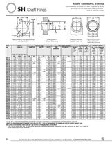
Axially Assembled, External Once installed in the groove of a shaft, the portion of the ring protruding from the groove (also called a "shoulder") holds an assembly in place. Free Diameter & Ring Measurements Shaft Diameter & Groove Dimensions Clearance Diameter Expanded Over Shaft Clearance Diameter & Gaging Diameter * F.I.M. (FULL INDICATOR MOVEMENT)- MAXIMUM ALLOWABLE DEVIATION OF CONCENTRICITY BETWEEN GROOVE & SHAFT. i BASED ON HOUSINGS/SHAFTS MADE OF COLD ROLLED STEEL. FOR AN EXPLANATION OF FORMULAS USED TO DERIVE THRUST LOAD AND OTHER PERFORMANCE DATA CONTACT THE ROTOR CLIP ENGINEERING...
Open the catalog to page 3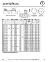
Maximum Corner Radius & Chamfer Exploded Groove Profile & Edge Margin (Y) Maximum bottom radii (R), sharp corners for ring sizes -12 thru -23; .003 for ring sizes -25 thru -35; .005 for sizes -37 thru -100; .010 for Alternate Design Manufacturer's Option FOR HARDNESS SPECIFICATIONS, SEE END OF THIS SECTION. For the most up-to-date specifications, online ordering, quotations & sample orders, visit www.rotorclip.com
Open the catalog to page 4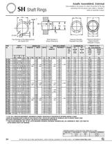
Axially Assembled, External Once installed in the groove of a shaft, the portion of the ring protruding from the groove (also called a "shoulder") holds an assembly in place. Free Diameter & Ring Measurements Shaft Diameter & Groove Dimensions Clearance Diameter Expanded Over Shaft Clearance Diameter & Gaging Diameter * F.I.M. (FULL INDICATOR MOVEMENT)- MAXIMUM ALLOWABLE DEVIATION OF CONCENTRICITY BETWEEN GROOVE & SHAFT. i BASED ON HOUSINGS/SHAFTS MADE OF COLD ROLLED STEEL FOR AN EXPLANATION OF FORMULAS USED TO DERIVE THRUST LOAD AND OTHER PERFORMANCE DATA CONTACT THE ROTOR CLIP ENGINEERING DEPARTMENT....
Open the catalog to page 5
Maximum Corner Radius & Chamfer Exploded Groove Profile & Edge Margin (Y) Maximum bottom radii (R), sharp corners for ring sizes -12 thru -23; .003 for ring sizes -25 thru -35; .005 for sizes -37 thru -100; .010 for Alternate Design Manufacturer's Option LARGER SIZES MAY BE AVAILABLE UPON REQUEST. HARDNESS RANGES: CARBON STEEL RINGS (SAE 1050-1090) HARDNESS RANGES: BERYLLIUM COPPER RINGS 1 HARDNESS CAM NOT BE CHECKED WITH ANY DEGREE OF ACCURACY DIRECTLY ON THESE RINGS. For the most up-to-date specifications, online ordering, quotations & sample orders, visit www.rotorclip.com
Open the catalog to page 6All Rotor Clip Company catalogs and technical brochures
 Company Overview
44 Pages
 Wave Spring Catalog
44 Pages
 Distribution Brochure
16 Pages
 Oil & Gas Industry Brochure
8 Pages
 Medical Industry Brochure
8 Pages
 Aerospace Industry Brochure
12 Pages
 Automotive Industry Brochure
12 Pages
 Product Catalog
276 Pages
 Wave Springs
8 Pages
 Rotor Clip Company Overview
44 Pages
 THE ULTIMATE RETAINING
72 Pages
 THE WORLD' QUALITY SOURCE
12 Pages
 Rotor Clip Oil & Gas
8 Pages
 Rotor Clip Wind Power
4 Pages


Archived catalogs
 SH
SH6 Pages
 E
E2 Pages
 BSH
BSH2 Pages
 DHI
DHI2 Pages
 DSH
DSH2 Pages
 DE
DE1 Page
 CFS
CFS3 Pages
 HO
HO6 Pages
 CTB
CTB1 Page
 Bearing Chart
3 Pages
 HO Shaft Rings
6 Pages
 HOI Shaft Rings
2 Pages
 BHO Shaft Rings
2 Pages
 VHO Shaft Rings
6 Pages
 SHR Shaft Rings
2 Pages
 SHI Shaft Rings
2 Pages
 SHM Shaft Rings
2 Pages
 BSH Shaft Rings
2 Pages
 VHS Shaft Rings
4 Pages
 LC Shaft Rings
2 Pages
 PO Shaft Rings
2 Pages
 Wave springs
12 Pages
 KMS Shims
1 Page
 HC Hose Clamps
1 Page
 Applicators and dispensers
3 Pages
 DHT
DHT2 Pages
 DHR
DHR1 Page
 DSH
DSH8 Pages
 DSI
DSI2 Pages
 Retaining Ring Kits
1 Page
 MKR series
2 Pages
 MKG
MKG2 Pages
 MKA
MKA2 Pages
 DCR
DCR2 Pages
 MCG
MCG2 Pages


- Rototherm clamping
- Rototherm spring
- Rototherm metal spring
- Rototherm hose clamp
- Rototherm wire spring
- Rototherm compression spring
- Stainless steel hose clamp
- Rototherm retaining ring
- Wire pliers
- Band hose clamp
- Rototherm steel spring
- Cable pliers
- Rototherm external retaining ring
- Rototherm internal retaining ring
- Chock
- Rototherm metric retaining ring
- Pipe pliers
- Clamping tool
- Steel hose clamp
- Lineman's pliers