- Catalogs
- Rotary Power
- XJ05-01/10/2025
XJ05-01/10/2025
1 /36Pages
XJ05-01/10/2025
1 /36Pages
Catalog excerpts
Product features Quick selection diagram Motor order code Torque unit single speed option Torque unit two speed option Shaft motor single speed with spline Shaft motor two speed with spline Shaft motor output options Shaft motor permissible dynamic and static radial load Wheel motor single speed option Wheel motor two speed option Wheel motor output options Wheel motor permissible dynamic and static radial load Parking brakes Direction of shaft rotation Hydraulic connections Torque output standard & increased displacements Static torque standard & increased displacements No load pressure drop...
Open the catalog to page 2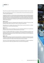
Rotary Power specialises in the design, development and manufacture of hydraulic motors and pumps. With a history dating back over 50 years, we understand the exacting and demanding requirements of today’s hydraulic applications. Operating from 18,000 sq. m. of purpose built manufacturing facilities, based in the North East of England and Bangalore, India, we continue to invest in the latest CNC machinery, automation and testing facilities. We have a clear focus on continuous improvement in lean cellular manufacturing. These facilities, alongside our European and US operations, offer sales, service...
Open the catalog to page 3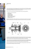
The XJ range of hydraulic motors offer displacements from 260 to 5,010 cc/rev. The XJ05 is the smallest of the range with displacements from 260 to 750 cc/rev, complemented by the larger XJ20 and XJ40 motors extending the displacement range to 2,505 and 5,010 cc/rev. The XJ motor has a range of features and options designed to suit your specific application: • • • • • • • • Radial piston, multi-stroke operation Modular design Two speed options Parking brake options Freewheel capability Multiple mounting arrangements 350 bar continuous pressure Fast delivery options The motor is designed with...
Open the catalog to page 4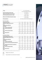
STANDARD DISPLACEMENTS *Maximum values should only be applied for a small portion of the duty cycle. Weight of motor without oil Sizes are listed in mm, inches shown in brackets
Open the catalog to page 5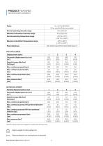
INCREASED DISPLACEMENTS *Maximum values should only be applied for a small portion of the duty cycle. Approx weight of motor without oil Sizes are listed in mm, inches shown in brackets
Open the catalog to page 6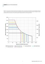
QUICK SELECTION DIAGRAM Based on your torque and speed requirements, the diagram below can be used to help determine which displacement best suits your application. Shown for both standard (solid lines) and increased (dashed lines) displacements, the diagram outlines the limits of the motor based on its continuous power rating and maximum continuous pressure. XJ05 - Quick Selection Diagram 4000 Maximum Available Torque (lbf.ft) Maximum Available Torque (Nm) Maximum Available Speed (rpm) 260 cc/rev [15.9 in³/rev] 503 cc/rev [30.7 in³/rev] 688 cc/rev [42 in³/rev] 376 cc/rev [22.9 in³/rev] 515 cc/rev...
Open the catalog to page 7
REAR BRAKE OPTIONS
Open the catalog to page 9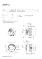
A3 (For models shown below) See Rotary Power for more details. Rotor spline Other spline options available, contact us for more information. See page 23 for hydraulic connection options.
Open the catalog to page 10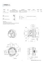
See Rotary Power for more details. (For models shown below) A 29kg without brake Rotor spline Other spline options available, contact us for more information. See page 23 for hydraulic connection options.
Open the catalog to page 11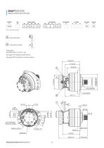
SHAFT MOTOR SINGLE SPEED WITH SPLINE (For models shown below) 44 kg without brake Shaft spline DIN 5480: W55 x 3 x 30 x 17 x 8f See page 14 for additional shaft options. See page 23 for hydraulic connection options. 222.5 8.76 181.5 7.15
Open the catalog to page 12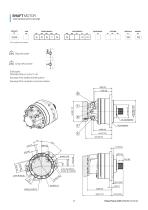
SHAFT MOTOR TWO SPEED WITH SPLINE (For models shown below) 52 kg without brake Shaft spline DIN 5480: W55 x 3 x 30 x 17 x 8f See page 14 for additional shaft options. See page 23 for hydraulic connection options. 169 6.65 159 6.26
Open the catalog to page 13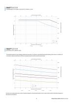
SHAFT MOTOR PERMISSIBLE DYNAMIC AND STATIC RADIAL LOAD Axial Position from End of Shaft (in) -0.2 0.0 0.2 Maximum Permissible Radial Load (kN) Maximum Permissible Radial Load (lbf) -25 -20 -15 Axial Position from End of Shaft (mm) Static SHAFT MOTOR BEARING LIFE UNDER LOAD The data illustrates the permissible radial load necessary to achieve a specified bearing life. Bearing life is shown in millions of revolutions. Data presented is at 150 bar average pressure, without external axial load. Axial Position from End of Shaft (in) -0.2 0.0 0.2 Maximum Permissible Radial Load (kN) Maximum Permissible...
Open the catalog to page 15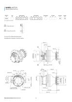
WHEEL MOTOR SINGLE SPEED OPTION (For models shown below) See page 19 for alternate wheel outputs. See page 23 for hydraulic connection options.
Open the catalog to page 16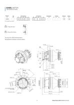
WHEEL MOTOR TWO SPEED OPTION (For models shown below) See page 19 for alternate wheel outputs. See page 23 for hydraulic connection options.
Open the catalog to page 17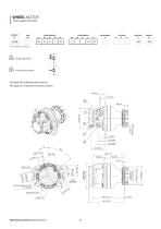
A3 (For models shown below) See page 19 for alternate wheel outputs. See page 23 for hydraulic connection options.
Open the catalog to page 18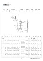
PRODUCT CAM FRONT MODULE PORT MODULE REAR BRAKE OPTIONS SPECIALS DESIGN
Open the catalog to page 19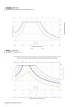
WHEEL MOTOR PERMISSIBLE DYNAMIC AND STATIC RADIAL LOAD Axial Position from End of Shaft (in) -0.8 120 Maximum Permissible Radial Load (kN) Maximum Permissible Radial Load (lbf) 0 Axial Position from End of Shaft (mm) Static WHEEL MOTOR BEARING LIFE UNDER LOAD The data illustrates the permissible radial load necessary to achieve a specified bearing life. Bearing life is shown in millions of revolutions. Data presented is at 150 bar average pressure, without external axial load. Axial Position from Wheel Flange (in) -5.9 120 Axial Position from Wheel Flange (mm) 8M Contact us for alternative duty...
Open the catalog to page 20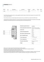
OPTIONS SPECIALS DESIGN Do not run in brake, wearing the plates will reduce the static capacity. Dynamic use of the brake is not recommended and should only be used in emergency situations. The disc pack should be replaced after ten dynamic uses. Times may vary depending on fluid viscosity and valves used. During low temperature applications, flushing the brake housing is recommended to maintain a constant oil viscosity. All data is based on ISO46 fluid at 40°C/[122°F]. If a different fluid will be used, please consult Rotary Power.
Open the catalog to page 21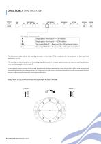
PRODUCT CAM FRONT MODULE PORT MODULE REAR BRAKE OPTIONS SPECIALS DESIGN The XJ motor code defines the starting direction of the motor. This is selected by the customer to best suit their application needs. The starting direction is based on flow being supplied to port A. A single speed motor can have its starting direction reversed by supplying flow to port B. In two speed motors, pressurising port A is preferred as this prevents the motor from recirculating high pressure oil when shifted into second displacement. It is important to select the correct starting direction of a two speed motor to...
Open the catalog to page 22All Rotary Power catalogs and technical brochures
 C RANGE PUMP
1 Page
 SMA MOTOR
2 Pages
 SMA Catalogue
15 Pages
 XJ20 Catalogue
32 Pages
 Rotary Power Company Overview
20 Pages
 XJ40 catalogue
28 Pages
Archived catalogs
 C | Range
9 Pages
 XJ05 catalogue
32 Pages
- Hydraulic pump
- Hydraulic piston pump
- High-pressure hydraulic pump
- Piston hydraulic motor
- Hydraulic axial piston pump
- Fixed-displacement hydraulic motor
- Industrial hydraulic motor
- Radial piston hydraulic motor
- High-torque hydraulic motor
- Hydraulic motor for heavy-duty applications
- Low-speed hydraulic motor
- Construction equipment hydraulic motor
- High-speed hydraulic motor
- Two-speed hydraulic motor