- Catalogs
- ROSS EUROPA
- Valve Installation & Service Manual
Valve Installation & Service Manual

Valve Installation & Service Manual
Catalog excerpts

Sol C C1C2 P Holding Pressure V1 V2 Sol ASol B L-O-X ί́ Valve >
Open the catalog to page 1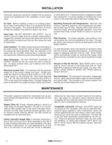
Pneumatic equipment should be installed only by personstrained and experienced in the installation of such equip-ment. Operating Pressures and Temperatures: Maximum andminimum operating pressures and temperatures are speci- fied for each type of valve. Staying within these limits con-tributes to longer valve life and proper operation. If you mustexceed these limits, consult ROSS for advice on such ser- vice. Air lines: Before installing a valve in an existing system,the air lines must be blown clean of all contaminants whichmay be in the system. It is recommended that a 5-micronair filter be...
Open the catalog to page 4
Varnish DepositsReturn Spring Figure 6- Precision Finished Stainless Steel SpoolValve Body for Base Mounting > BROKEN RETURN SPRING A broken return spring on a spool valve (see Figure 6) cancause the spool to remain in an actuated position, or to be onlypartially returned. In the latter case, several abnormal flow patternsmay result depending on the valve configuration. If a spool valve has anormal flow pattern only in an actuated position, a broken return springis the most likely cause of the trouble.A broken return spring on an inline poppet valve is less likely to preventclosing of the inlet...
Open the catalog to page 8
CYLINDER LEAKS See figure 10. Four-way valves sometimes blow to ex-haust because of leaking packings in the work cylinderconnected to the valve. Before looking for faults in the valve, checkthe cylinder for leaks. In the following steps, take appropriate safetyprecautions because both the valve and the cylinder will be actu-ated. > PILOT SECTION - DIRTY OR DAMAGED INSERT Turn off electrical power to valve. Shut off the air supplyand exhaust air in the system. Follow appropriate lock-out/tag-out procedures. Disassemble the pilot section. For pilotsshown in Figure 7 or 8, remove pilot insert. Check...
Open the catalog to page 9
Figure 11- Pilot Section of Valves for Size 1.5 andISO Bases Figure 12- Flow Control Valve > UNDERSIZE OR PLUGGED SILENCER An undersize silencer, or one that is partiallyplugged,restricts the exhaust flow. The resulting back pressurecan cause erratic motion of poppet valve elements and/or cylin-ders. Remove silencer to see if valve performance is improved.Clean silencer and verify that it is of adequate size. Do not reinstallan undersize silencer. Install cleaned or larger size silencer andcheck valve performance again. FLUCTUATING AIR PRESSURE If a valve with a timed sequence adaptor suffers...
Open the catalog to page 10
ROSS CONTROLSROSS CONTROLSROSS CONTROLSROSS CONTROLSROSS CONTROLS > ήή P.O. Box 7015Troy, Michigan 48007 U.S.A. Telephone (00) 1-248-764-1800 Fax (00) 1-248-764-1850 www.rosscontrols.com In the United States: Customer Service: 1-800-GET-ROSS Technical Service: 1-800-TEK-ROSSROSS/FLEX ή Service: 1-888-ROSS-FLX ROSS EUROPA GmbH ROSS UK Ltd. > Robert-Bosch-Stra βββββ e 2D-63225 Langen, Germany Telephone (011) 49-6103-7597-0 Fax (011) 49-6103-7469-4 St. James Road, BrackleyNorthamptonshire NN13 7XY United Kingdom Telephone (011) 44-1280-706668 Fax (011) 44-1280-705630 ROSS ASIA K.K. > 10209-5 Tana,...
Open the catalog to page 12All ROSS EUROPA catalogs and technical brochures
 E505E
E505E16 Pages
 E-RE-08
68 Pages
 E620D
E620D20 Pages
 E481
E4815 Pages
 D385B
D385B30 Pages
 E425F
E425F29 Pages
 ROSS/FLEX® - Profile
1 Page
 Pinch Valves
9 Pages
 E104
E104110 Pages
 E372A
E372A20 Pages
 E485
E48520 Pages
 Series 80 and 84
4 Pages
 Series W70 and W74
7 Pages
 Series W65
5 Pages
 Series W60, W63 and W64
7 Pages
 Series D21
2 Pages
 Series D27
3 Pages
 Pneumatic Machine Safeguarding
32 Pages
 DM2 - Double Valves
20 Pages
 E200
E20028 Pages
Archived catalogs
 ISO/VDMA-Standard, Size 0
6 Pages
 ISO Valves for Base Mounting
28 Pages
 Compact Valves
24 Pages
 ROSS-Safety-related valves
12 Pages


