- Catalogs
- ROSS EUROPA
- E505E
E505E
1 /16Pages

E505E
1 /16Pages
Catalog excerpts

3/2 Double Valves with Dynamic Monitoring & Dynamic Memory Manufacturers of Premium Pneumatic Controls since 1921.
Open the catalog to page 1
Table of Contents DM2® Series D Double Valves General Information Ordering Information Valve Dimensions Overview of DM2® Series D Double Valves Valve Response Charts Operating Instructions Repair Kits The Leader in Double Valve Design. ROSS has long been in the forefront of double valve research and development. For over 60 years ROSS has been responding to the needs of press manufacturers and users by progressively improving double valve technology. Internal flow patterns of double valves developed by ROSS have included series flow, parallel flow, combined series-parallel tandem flow, and combined...
Open the catalog to page 2
DM2® Series D Double Valves The ROSS DM 2® Series D double valves provide significant features in response to the changing demands of the mechanical press industry and its associated standards (e.g. EN 692 ff.) and regulations regarding the control of pneumatically controlled clutch and brake applications. The consensus requirements of the regulations and good practices require that, in case of a failure within the valve, the clutch and brake mechanisms be quickly exhausted, a monitor takes action to prevent further operation, and a method to alert personnel is incorporated. These features also...
Open the catalog to page 3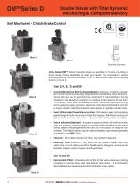
Double Valves with Total Dynamic Monitoring & Complete Memory Self Monitored - Clutch/Brake Control Size 4 Size 2 Simplified Schematic Valve Sizes: DM2® Series D double valves are available in 5 sizes, providing a broad range of flow capabilities to meet your needs. For convenience, valves are designated by the nominal sizes 2, 4, 8, 12, and 30 with outlet ports ranging from G 1/4 to G 2. Size 2, 4, 8, 12 and 30 • Dynamic Monitoring With Complete Memory: Memory, monitoring, and air flow control functions are simply integrated into two identical valve elements. Valves lock-out due to asynchronous...
Open the catalog to page 4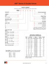
DM2® Series D Double Valves HOW TO ORDER (Choose your options (in red) to configure your valve model number.) REVISION LEVEL BASIC SIZE Valve Weight: Valve and base assembly with status indicator and solenoid reset. Size 2: 2.3 kg RESET TYPE ** 220 VAC not available in the U.S. (OSHA regulations limit press control voltage to no more than 120 volts AC). BASE MODEL NUMBERS and BASE SPECIFIC INFORMATION Valve Port Size Base Status Weight Size Inlet Outlet Model Number* Indicator kg *BSPP port threads. For NPT threads omit letter “D”. Example: 1872C91.
Open the catalog to page 5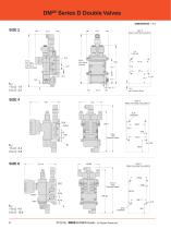
DM2® Series D Double Valves DIMENSIONS – mm View X (Base mounting hole pattern) 5.6 (4 places) 30.2 270.0 With Status Indicator & Solenoid Reset 253.8 With Status Indicator 16.3 with Solenoid Reset View X (Base mounting hole pattern) View X (Base mounting hole pattern) © 2016, ROSS EUROPA GmbH.
Open the catalog to page 6
DM2® Series D Double Valves DIMENSIONS – mm View X (Base mounting hole pattern) 320.23 with Pressure Switch 286.26 View X (Base mounting hole pattern) 393.14 with Pressure Switch 361.98 kV : 1 to 2: 17.6 2 to 3: 46.7 STANDARD SPECIFICATIONS Pilot Solenoids: According to VDE 0580. Enclosure rating according to DIN 40050, IEC 60529 IP65. Two solenoids, rated for continuous duty (additional solenoid on optional reset). Standard Voltages: 24 volts DC; 110 volts AC, 50/60 Hz. For other voltages, consult ROSS. Power Consumption (each solenoid): Size 2, 4, 12, 30: For primary and reset solenoids: 6.0...
Open the catalog to page 7
Overview of DM2® Series D Double Valve Function Valve de-actuated (ready-to-run): The flow of inlet air pressure into the crossover passages is restricted by the size of the passage between the stem and the valve body opening. Flow is sufficient to quickly pressurize pilot supply/timing chambers A and B. The inlet poppets prevent air flow from crossover passages into the outlet chamber. Air pressure acting on the inlet poppets and return pistons securely hold the valve elements in the closed position. (Air passages shown out of position and reset adapter omitted for clarity. EXHAUST S EXHAUST...
Open the catalog to page 8
Overview of DM2® Series D Double Valve MAIN VALVE INTERNALS Pilot Valve B Pilot supply/timing chamber A Piston Exhaust chamber Exhaust poppet Outlet chamber Inlet poppet Timing orifice Crossover passages Inlet chamber Flow restrictor INLET Reset poppet Spring stop Reset piston Return spring VALVE SCHEMATIC
Open the catalog to page 9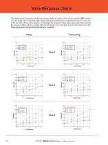
Valve Response Charts The charts below represent the fill and exhaust times for each of the various sizes of DM2® valves. The “fill” times were measured while raising (filling) the pressure in a volume from 0 to 2, 0 to 4, & 0 to 5,4 bar with a 6 bar inlet pressure. Conversely, the “exhaust” times were measured while lowering the pressure (exhausting) in a volume from 6 bar down to 4, 6 bar down to 2, & 6 bar down to 0,6 bar. Exhausting tests performed with silencer installed. Volume litres Volume litres Volume litres Volume litres Volume litres Volume litres © 2016, ROSS EUROPA GmbH.
Open the catalog to page 10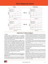
Valve Response Charts Filling Volume litres Volume litres Volume litres Volume litres Application & Safety Category 1. General The design features of the DM 2® Series D are of considerable importance to users of double valves, such as on mechanical power press applications (EN 692) and other critical applications. This is because the DM 2® Series D is designed to meet the latest standards requiring (EN 954) “control reliable”, “Category-3 & -4”, or “dynamic monitoring” capability. Both the monitoring and memory capabilities of the DM2® Series D valve are built in to the two piston-poppet stem...
Open the catalog to page 11
Start-up Before start-up, the installation must be checked thoroughly by persons trained and experienced in the operation of pneumatic equipment. Make sure that specifications given on the valve label (e.g. “max. operating pressure” and “electrical characteristics”) will be in accordance with the operating specifications of the press. When operating pressure is initially applied, it may be necessary to actuate the reset valve momentarily to move the main valve into the ready-to-run condition. Make sure that the inlet supply and the exhaust path are not restricted. Operating pressure must comply...
Open the catalog to page 12All ROSS EUROPA catalogs and technical brochures
 E-RE-08
68 Pages
 E620D
E620D20 Pages
 E481
E4815 Pages
 D385B
D385B30 Pages
 E425F
E425F29 Pages
 ROSS/FLEX® - Profile
1 Page
 Pinch Valves
9 Pages
 E104
E104110 Pages
 E372A
E372A20 Pages
 E485
E48520 Pages
 Series 80 and 84
4 Pages
 Series W70 and W74
7 Pages
 Series W65
5 Pages
 Series W60, W63 and W64
7 Pages
 Series D21
2 Pages
 Series D27
3 Pages
 Pneumatic Machine Safeguarding
32 Pages
 DM2 - Double Valves
20 Pages
 E200
E20028 Pages
Archived catalogs
 ISO/VDMA-Standard, Size 0
6 Pages
 ISO Valves for Base Mounting
28 Pages
 Compact Valves
24 Pages
 ROSS-Safety-related valves
12 Pages


- Control valve
- Water valve
- Cylinder
- Actuator
- Threaded valve
- Flap valve
- Check valve
- Gas valve
- Directional control valve
- Double-acting cylinder
- Hydraulic cylinder
- Pneumatic cylinder
- Compact valve
- Single-acting cylinder
- Pneumatic directional control valve
- Compact cylinder
- Threaded check valve
- Rotary actuator
- Aluminum valve