Catalog excerpts

SERIES W60 SPOOL VALVES – Solenoid Control ISO 5599/I - Drop Cord Connections 4 STANDARD SPECIFICATIONS Solenoids: Rated for continuous duty. Standard voltages: 100–110 volts 50 Hz.; 100–120 volts 60 Hz.; 24, 110 volts d.c. Power Consumption: 8.5 VA inrush; 6 VA holding on 50 or 60 Hz.; 6 watts on d.c. Ambient Temperature: 40 to 120° F (4 to 50° C). Media Temperature: 40 to 175° F (4 to 80° C). Flow Media: 5 micron filtered air. Inlet Pressure: Vacuum to 150 psig (10 bar). Pilot Pressure: Size 1: At least 30 psig (2 bar). Size 2 and 3: At least 15 psig (1 bar). 5/2 Single Solenoid Pilot Valve Sub-Bases & Manifolds: Page 14. Connectors, Electrical: Page 15. Regulators & Flow Controls, Interposed: Page 15. Locking Overrides: See note below.§ GM PS-1 models with 3-pin mini-connectors: See note below. 5/2 Double Solenoid Pilot Valve IMPORTANT NOTE Please read carefully and thoroughly the CAUTIONS on page 23. **VALVE RESPONSE TIME (msec) = M + (F • V) Average time required to fill volume V (cubic inches) to 90% of supply pressure or to exhaust it to 10% of supply pressure. M and F values are shown in charts for each valve. See discussion of Valve Response Time on page 22. 5/3 Open or Closed Center Valve Open Center 5/2 SINGLE SOLENOID PILOT VALVES Avg. Response Constants** Avg. Cv 0.9 1.9 3.9 Valve Model Number§ Port Sizes* 5/2 DOUBLE SOLENOID PILOT VALVES 0.9 1.9 3.9 5/3 CLOSED CENTER DOUBLE SOLENOID PILOT VALVES 0.9 1.9 3.9 5/3 OPEN CENTER DOUBLE SOLENOID PILOT VALVES 0.9 1.9 3.9 Models with locking overrides can be ordered by changing the 9th digit of model number to “1”. For example, W6076B2411. For models with 3-pin mini-connectors that conform to G.M. PS-1 standards, change the 9th digit to “3”. For example, W6076B2431. * Port sizes determined by customer’s choice of base or manifold. Bases and manifolds sold separately – see page 14. † Height of valve with electrical connector installed. Connectors sold separately – see page 15. ROSS CONTROLS®
Open the catalog to page 1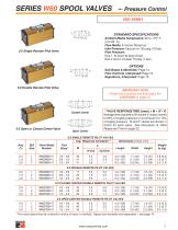
SERIES W60 SPOOL VALVES – STANDARD SPECIFICATIONS Ambient/Media Temperature: 40 to 175° F (4 to 80° C). Flow Media: 5 micron filtered air. Inlet Pressure: Vacuum to 150 psig (10 bar). Pilot Pressure: Size 1: At least 30 psig (2 bar). Size 2 and 3: At least 15 psig (1 bar). 5/2 Single Remote Pilot Valve Sub-Bases & Manifolds: Page 14. Flow Controls, Interposed: Page 15. Regulators, Interposed: Page 15. 5/2 Double Remote Pilot Valve IMPORTANT NOTE Please read carefully and thoroughly the CAUTIONS on page 23. 4 **VALVE RESPONSE TIME (msec) = M + (F • V) Average time required to fill volume V...
Open the catalog to page 2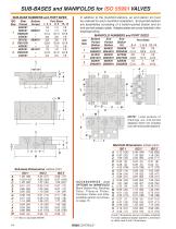
SUB-BASES and MANIFOLDS for ISO 5599/I VALVES SUB-BASE NUMBERS and PORT SIZES ISO Size 1 In addition to the manifold stations, an end station kit must be ordered for each manifold installation. End-ported stations are assemblies consisting of a bottom-ported station and an end-ported adaptor plate. Adaptor plates are cross-hatched in the drawings below. MANIFOLD NUMBERS and PORT SIZES NOTE: Lined portions of drawings are end-ported adaptors which are included only with end-ported stations. Manifold Dimensions inches (mm) Sub-base Dimensions inches (mm) A B C D E F G H I J K L M ACCESSORIES...
Open the catalog to page 3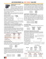
ACCESSORIES for ISO 5599/I VALVES CONNECTORS for use with DROPCORDS Electrical connectors are required to connect the valve solenoids to the dropcords supplying electrical power. Each connector can be oriented so that the cord can exit in any one of four directions: outboard, inboard, and to the right or to the left of the valve centerline. Cords of 6-mm to 10-mm diameter can be used. Indicator Lights. Lights in connectors with a translucent housing can be used as indicator lights to show when solenoids are energized. Wired Connectors. Connectors have a 6-1/2- ft (2-meter) cord with three...
Open the catalog to page 4All ROSS Controls catalogs and technical brochures
-
safety product
32 Pages
-
Line-Mount Valves
16 Pages
-
DM2
4 Pages
-
MD3
16 Pages
-
CM series
4 Pages
-
Press Industry Solutions
28 Pages
-
DM2 Series D
16 Pages
-
Safety-Related Products
32 Pages
-
Fluid Power Safety Overview
4 Pages
-
Modular Pneumatic Solutions
8 Pages
-
Drip Leg Drains
2 Pages
-
ISO 5599 I and II VDMA 24563
20 Pages
-
Series 80 and 84 SAE Std
12 Pages
-
Series 70 and 74
12 Pages
-
L -O-X ® V a l v es
4 Pages
-
foot valves
1 Pages
-
manual valve
12 Pages
-
Pilot operated check valves
12 Pages
-
safety valve
13 Pages
-
FRL ROSS
12 Pages
-
poppet valve
16 Pages
-
TSSA
48 Pages
Archived catalogs
-
ENERGYSAVER® Valve
2 Pages
-
Ross regulators
2 Pages
-
serial bus system
29 Pages
-
Dale series poppet valves
16 Pages


