Catalog excerpts
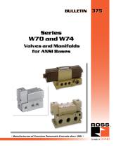
Valves and Manifolds for ANSI Bases • Manufacturers of Premium Pneumatic Controls since 1921 •
Open the catalog to page 1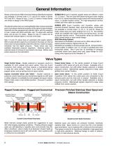
General Information Bases conforming to ANSI (American National Standards Institute) are available in nominal sizes 4, 10, and 20 for valves in Series W70 and W74. Bases for size 1.5 and 2.5 valves in these Series are similar in design to the ANSI bases. All solenoid valves have non-locking flexible-button manual overrides and a 5-pin plug-in electrical connector at the valve-to-base interface. Solenoids are also equipped with indicator lights, with the exception of size 4 valves with direct solenoids, size 1.5 valves with solenoid pilots, and all size 2.5 valves. Bases for size 2.5 valves...
Open the catalog to page 2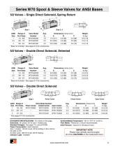
Series W70 Spool & Sleeve Valves for ANSI Bases 5/2 Valves – Single Direct Solenoid, Spring Return A Size 1 Range of Port Sizes 1/4 - 3/8 3/8 - 1/2 Valve Model Number* W7016A2331 W7016A3331 * Base not included. See pages 8-10 for accessories. 5/2 Valves – Double Direct Solenoid, Detented A Size 1 Range of Port Sizes 1/4 - 3/8 3/8 - 1/2 Valve Model Number* W7016A2332 W7016A3332 * Base not included. See pages 8-10 for accessories. 5/3 Valves – Double Direct Solenoid A Closed Center Open Center Power Center Size 1 ANSI Range of Valve Model Number* Size Port Sizes Power Center Closed Center...
Open the catalog to page 3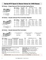
Series W70 Spool & Sleeve Valves for ANSI Bases 5/2 Valves – Single Solenoid Pilot Controlled, Spring Return * Base not included. See pages 8-10 for accessories. 5/2 Valves – Double Solenoid Pilot Controlled, Detented A C * Base not included. See pages 8-10 for accessories. 5/3 Valves – Double Solenoid Pilot Controlled A 4 Power Center Closed Center B ANSI Range of Valve Model Number* Size Port Sizes Power Center Closed Center Open Center Open Center * See pages 8-10 for accessories. STANDARD SPECIFICATIONS: For valves on this page. Solenoids: AC or DC power. Standard Voltages: See page...
Open the catalog to page 4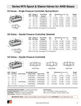
Series W70 Spool & Sleeve Valves for ANSI Bases 5/2 Valves – Single Pressure Controlled, Spring Return ANSI Range of Size Port Sizes Valve Model Number* W7056A2331 * Base not included. See pages 8-10 for accessories. 5/2 Valves – Double Pressure Controlled, Detented ANSI Range of Size Port Sizes Valve Model Number* W7056A2332 * Base not included. See pages 8-10 for accessories. 5/3 Valves – Double Pressure Controlled A C Closed Center Power Center ANSI Range of Valve Model Number* Size Port Sizes Power Center Closed Center Open Center 1 Open Center * Base not included. See pages 8-10 for...
Open the catalog to page 5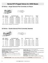
Series W74 Poppet Valves for ANSI Bases 5/2 Valves – Single Solenoid Pilot Controlled, Air Return A C ANSI Range of Valve Model Number* Size Port Sizes Std. Temp. High Temp. * Base not included. See pages 8-10 for accessories. 5/2 Valves – Double Solenoid Pilot Controlled, Detented A C ANSI Range of Valve Model Number* Size Port Sizes Std. Temp. High Temp. * Base not included. See pages 8-10 for accessories. STANDARD SPECIFICATIONS: For valves on this page. Solenoids: AC or DC power. Standard Voltages: See page 110; consult ROSS. Power Consumption: Each solenoid. Size 1 models: 10 VA...
Open the catalog to page 6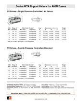
Series W74 Poppet Valves for ANSI Bases 5/2 Valves - Single Pressure Controlled, Air Return ANSI Range of Valve Model Number* Avg. Dimensions inches (mm) Weight Size Port Sizes Std.Temp. High Temp. Cv A B C lb (kg) * Base not included. See pages 8-10 for accessories. 5/2 Valves - Double Pressure Controlled, Detented ANSI Range of Valve Model Number* Avg. Dimensions inches (mm) Weight Size Port Sizes Std.Temp. High Temp. Cv A B C lb (kg) * Base not included. See pages 8-10 for accessories. STANDARD SPECIFICATIONS: For valves on this page. Ambient/Media Temperature: 40° to 175°F (4° to 80°C);...
Open the catalog to page 7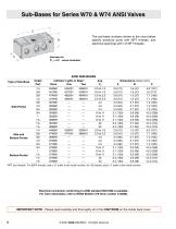
Sub-Bases for Series W70 & W74 ANSI Valves C The sub-base numbers shown in the chart below specify pressure ports with NPT threads, and electrical openings with 1/2 NPT threads. Sub-base for CV = 4.2 valves illustrated. ANSI SUB-BASES Type of Sub-Base Side-Ported Side and Bottom-Ported Bottom-Ported *NPT port threads. For BSPP threads, add a “D” prefix to the model number; for JIS threads, add a “J” prefix to the model number. Electrical connection conforming to ANSI standard B93.55M is available. For more information, refer to ROSS Bulletin 379 (form number A10090). IMPORTANT NOTE: Please...
Open the catalog to page 8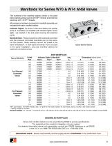
Manifolds for Series W70 & W74 ANSI Valves The numbers of the manifold stations shown in the chart below specify pressure ports with N PT threads and electrical openings with VA NPT threads. All necessary hardware and seals for manifold assembly are included with each manifold station. Indicator Lights: As shown in the chart below, the smaller sizes of manifolds are available with indicator lights. These lights are located in the end plate covering the electrical Manifold Note: Theportpositionsofthesolenoidcontrolled and the pressure controlled manifolds are not the same. For this reason...
Open the catalog to page 9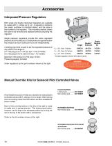
Accessories Interposed Pressure Regulators Both single and double interposed regulators are available for valves with CV ratings up to 4.2. A regulator is bolted to the valve’s sub-base or manifold station, and the valve is then bolted to the regulator. This mounting method allows the valve to be removed and replaced without disturbing the regulator. Single pressure regulators provide the same regulated pressure at both outlet ports. Double pressure regulators allow the pressure at each outlet port to be set independently. A locking type knob is used to set the regulated pressure at any...
Open the catalog to page 10
Cautions PRE-INSTALLATION or SERVICE 1. Before servicing a valve or other pneumatic component, be sure that all sources of energy are turned off, the entire pneumatic system is shut off and exhausted, and all power sources are locked-out (ref: OSHA 1910.147, EN 1037). 2. All ROSS products, including service kits and parts, should be installed and/or serviced only by persons having training and experience with pneumatic equipment. Because any installation can be tampered with or need servicing after installation, persons responsible for the safety of others or the care of equipment must...
Open the catalog to page 11All ROSS Controls catalogs and technical brochures
-
safety product
32 Pages
-
Line-Mount Valves
16 Pages
-
DM2
4 Pages
-
MD3
16 Pages
-
CM series
4 Pages
-
Press Industry Solutions
28 Pages
-
DM2 Series D
16 Pages
-
Safety-Related Products
32 Pages
-
Fluid Power Safety Overview
4 Pages
-
Modular Pneumatic Solutions
8 Pages
-
Drip Leg Drains
2 Pages
-
ISO 5599 I and II VDMA 24563
20 Pages
-
Series 80 and 84 SAE Std
12 Pages
-
L -O-X ® V a l v es
4 Pages
-
W60
4 Pages
-
foot valves
1 Pages
-
manual valve
12 Pages
-
Pilot operated check valves
12 Pages
-
safety valve
13 Pages
-
FRL ROSS
12 Pages
-
poppet valve
16 Pages
-
TSSA
48 Pages
Archived catalogs
-
ENERGYSAVER® Valve
2 Pages
-
Ross regulators
2 Pages
-
serial bus system
29 Pages
-
Dale series poppet valves
16 Pages


