
- Catalogs
- ROSS Controls
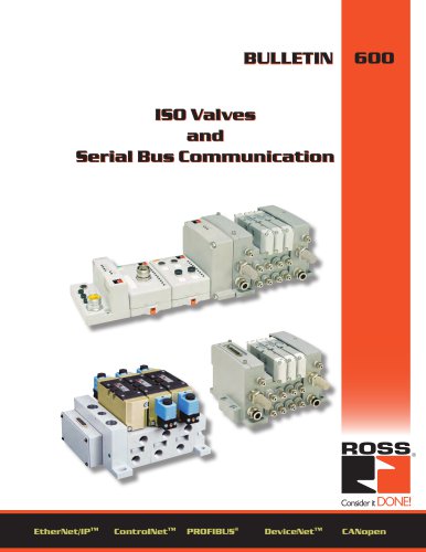
- serial bus system

serial bus system

1 / 29 PagesView full catalog
serial bus system
Product catalog summary
Warning and Responsibility: The document stresses the importance of selecting and using ROSS CONTROLS products correctly to prevent hazards such as death, injury, and property damage. Users must analyze applications to ensure safety and performance requirements are met.
Standard Definitions: It outlines standards for valve sizes, including ISO 15407-1, 15407-2, 5599-1, and 5599-2 for various valve sizes.
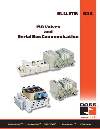
Serial Bus System Overview: Describes a Serial Bus communication system for ISO valves with UL, C-UL, and CE certifications, detailing centralized and remote configurations, and I/O density per module.
Communication Modules and Modularity: Supports up to 63 I/O modules with 264 inputs/outputs, featuring easy module replacement, auto device replacement, and built-in grounding and keying.
Integrated Solution: Offers fast I/O backplane performance, accepts signals from various input devices, and provides signals to output devices, including digital, analog, and high watt I/O modules.
Product Compatibility: Lists compatibility with network adapters like DeviceNet, ControlNet, EtherNet/IP, and PROFIBUS, detailing module support and power supply requirements.
Communication Considerations: Discusses the impact of network choice on Serial Bus features, with details on DeviceNet, ControlNet, EtherNet/IP, and PROFIBUS configurations.
Specifying a Serial Bus System: Steps include selecting a communication interface module, choosing I/O devices, selecting power components, and determining necessary accessories and configurations.
Network Selection: Provides guidance on selecting the appropriate network based on application requirements, such as plant management and high-speed data transfer.
Overview: Details specifications and guidelines for selecting and configuring Serial Bus I/O modules, power units, and accessories for industrial automation systems.
1. Serial Bus I/O Modules:
- Digital I/O Modules: Offer input filtering, optical isolation, and surge suppression with diagnostics for field-side issues.
- Analog I/O Modules: Feature channel-level data alarming, on-board scaling, and diagnostics with high accuracy.
- Relay Output Module: Provides isolated relay outputs with specific delay times and current leakage specifications.
- Valve Driver Module: Interfaces with valve assemblies, controlling up to 32 digital outputs at 24VDC.
2. Power Units:
- Power Supply Units: Include built-in power supplies and expansion units for up to 13 I/O modules.
- Power Distribution: Outlines configurations for power distribution, supporting up to 63 I/O modules.
3. Cables and Cordsets:
- Recommendations for cables and cordsets, specifying part numbers and compatible lengths.
Key Specifications:
- Digital I/O modules support various voltage interfaces and offer isolated and non-isolated types.
- Analog modules provide high accuracy with configurable parameters and diagnostics.
- Power units comply with safety standards, offering reverse polarity and overvoltage protection.
Maintenance Program: A maintenance program is crucial for valve and FRL longevity, with frequency based on application severity, risks, and past failures.
Installation and Service Instructions: Consult service bulletins or instruction sheets before servicing or replacing parts.
Lockout/Tagout Procedures: Follow ANSI/ASSE Z244.1-2003 and OSHA Standard 29 CFR, Part 1910.147, Appendix A.
Visual Inspection: Immediate shutdown and replacement are required for air leakage, damaged components, or improper function.
Environmental Considerations: Products are for general industrial use; exposure to sunlight or corrosive environments can cause failure.
Lubrication and Compressor Carryover: Check compatibility of synthetic oils with seal materials.
Polycarbonate Bowls and Sight Glasses: For compressed air applications only; avoid sunlight, impact, or incompatible cleaning agents.
Routine Maintenance: Keep work areas clean and ensure all guards and shields are in place.
Functional Test: Manually operate the system before automatic operation to ensure proper function.
Service or Replacement Intervals: Establish intervals based on past performance, standards, and risks.
Servicing or Replacing Parts: Follow safety practices, including OSHA Lockout/Tagout procedures, and ensure knowledgeable personnel perform servicing.
Reactivating Serviced Systems: Follow guidelines to ensure proper function after servicing.
See more
All ROSS Controls catalogs and technical brochures
 safety product
32 Pages
 Line-Mount Valves
16 Pages
 DM2
DM24 Pages
 MD3
MD316 Pages
 CM series
4 Pages
 Press Industry Solutions
28 Pages
 DM2 Series D
16 Pages
 Safety-Related Products
32 Pages
 Fluid Power Safety Overview
4 Pages
 Modular Pneumatic Solutions
8 Pages
 Drip Leg Drains
2 Pages
 ISO 5599 I and II VDMA 24563
20 Pages
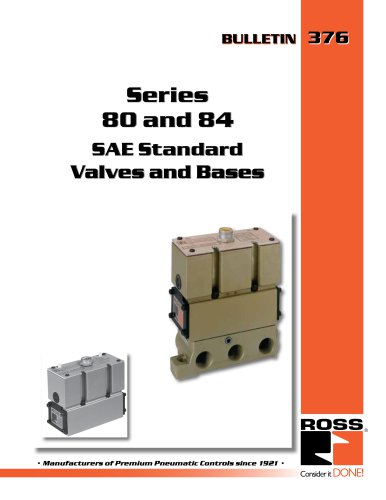 Series 80 and 84 SAE Std
12 Pages
 Series 70 and 74
12 Pages
 L -O-X ® V a l v es
4 Pages
 W60
W604 Pages
 foot valves
1 Page
 manual valve
12 Pages
 Pilot operated check valves
12 Pages
 safety valve
13 Pages
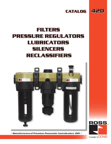
 FRL ROSS
12 Pages
 poppet valve
16 Pages
 TSSA
TSSA48 Pages







Archived catalogs
 ENERGYSAVER® Valve
2 Pages
 Ross regulators
2 Pages
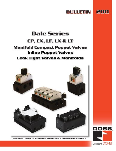
 Dale series poppet valves
16 Pages

Related Searches
- Manual valve
- Stainless valve
- Electrically operated valve
- Regulating valve
- On/off valve
- Gas solenoid valve
- 2-way solenoid valve
- NC solenoid valve
- Directional control valve
- Pressure limiter
- Direct-operated solenoid valve
- Single-stage pressure regulator
- Lift valve
- Industrial pressure limiter
- Air solenoid valve
- Pilot-operated solenoid valve
- Pneumatic directional control valve
- NO solenoid valve
- 3-way solenoid valve
*Prices are pre-tax. They exclude delivery charges and customs duties and do not include additional charges for installation or activation options. Prices are indicative only and may vary by country, with changes to the cost of raw materials and exchange rates.
About DirectIndustry
DirectIndustry is a marketplace that offers B2B players a complete experience, from product sourcing to purchase. DirectIndustry is an entity of VirtualExpo Group.
Are you a buyer?
Are you a supplier?