Catalog excerpts
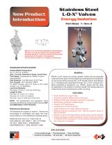
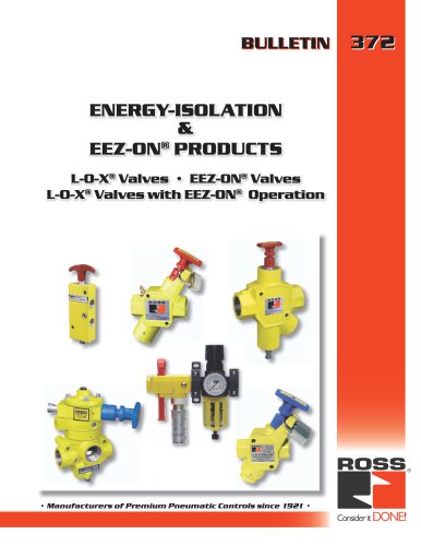
Stainless Steel L-O-X® Valves Energy Isolation Port Sizes ¼ thru 2 Manual L-O-X® valve shown padlocked in closed position. The valve can only be locked in the closed position. Push/pull operation - Push the handle inward to exhaust downstream air (lockable in this position). Pull the handle outward in to supply air downstream. STANDARD SPECIFICATIONS: Ambient/Media Temperature: 40° to 175°F (4° to 80°C). Note: For lower temperature ratings, consult Ross. Flow Media: Compressed air, ltered; 5 micron recommended. Inlet Pressure: 0 to 300 psig (0 to 20.7 bar). Port Threads: NPT standard, BSPP. For BSPP threads, add a “D” prex to the model number, e.g., D1523A2004. Lock Hole Diameter: Port sizes 1/4 thru 2: 0.34 inch (8.64 mm). Length of Hole: Port size 1/4: 0.44 in (11.17mm). Port size 1/2: 0.47 in (11.93mm) Port size 1 and 2: 0.55 inch (13.97 mm). NOTE: Per specications and regulations, these products are dened as energy isolation devices, NOT AS EMERGENCY STOP DEVICES. Referenced Standards: All standards are subject to revision. Parties are encouraged to investigate and apply the most recent editions of the standards indicated below. OSHA 29 CFR 1910.147; CSA Z142-10 CSA Z460-05; ISO 13849-1; ISO 14118:2000 EN 1037; ANSI Z244.1- 2003(R2008) ANSI/PMMI B155.1- 2006, ANSI B11-2008 ROSS L-O-X® valves are energy isolation valves and are generally used as the rst valve in a line supplying compressed air to equipment. Air can be shut off by pushing the L-O-X® handle inward; downstream air is simultaneously exhausted through the L-O-X® exhaust por t. Many standards & regulations, e.g., OSHA, require that the valve be padlocked in this position to prevent handle from being pulled out inadvertently during maintenance and/or servicing. Easily identied by unique shape Corrosion-resistant stainless steel construction Reliable VITON seals withstand contaminant ingression Self-draining, washdown suitable design Trusted L-O-X® performance Lockable only in the OFF position Large exhaust port for rapid release of pressure Standard pressure sensing port with optional pressure switch or pop-up indicator • Simple push/pull of the large handle provides direct manual operation • Pressure sensing port allows installation of either the Pop-Up Indicator or Pressure switch (see page 2) to verify pressure downstream to the next obstruction is released. APPLICATIONS: • Food and Beverage • Pharmaceutical • Pulp and Paper • Chemical Processing • Oil and Gas • Off-shore Industries
Open the catalog to page 1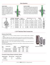
Valve Operation VALVE OPEN When the handle is pulled out, supply air flows freely from inlet to outlet and flow to exhaust is blocked. A detent keeps the handle in the open position. The handle is not designed to be locked in this position, thereby providing for ready shut-off when necessary. VALVE CLOSED With a push of the handle inward, the flow of supply air is blocked and downstream air is exhausted via the exhaust port while servicing or maintaining machinery. Padlock the L-O-X® valve in this position OUT to prevent the handle from being pulled outward inadvertently to avoid potential...
Open the catalog to page 2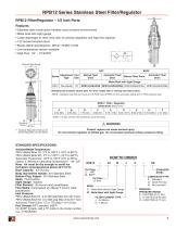
RPB12 Series Stainless Steel Filter/Regulator RPB12 Filter/Regulator – 1/2 Inch Ports Features • Stainless steel construction handles most corrosive environments • Metal bowl with sight gauge • Large diaphragm to valve area ratio for precise regulation and high flow capacity • 1/8" female threaded drain • Meets NACE specifications MR-01-75/ISO-15156 • Low temperature version available • High Flow: 1/2" – 72 SCFM* ä Optional Sight Gauge A1 Adjustment Port Series Type Size Manual Twist Drain Automatic Float Drain Manual Twist Drain Automatic Float Drain Metal Bowl with Sight Gauge PB12...
Open the catalog to page 3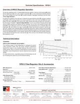
Technical Specifications – RPB12 Overview of RPB12 Regulator Operation A Turning the adjusting knob / T-Handle (A) clockwise applies a load to control spring (B) which forces diaphragm (C) and valve poppet assembly (D) to move downward allowing filtered air to flow through the seat area (E) created between thepoppet assembly and the seat. “First stage filtration”. Air pressure supplied to the inlet port is directed through deflector plate (F) causing a swirling centrifugal action forcing liquids and coarse particles to the inner bowl wall (G) and down below the lower baffle (H) to the quiet...
Open the catalog to page 4All ROSS Controls catalogs and technical brochures
-
safety product
32 Pages
-
Line-Mount Valves
16 Pages
-
DM2
4 Pages
-
MD3
16 Pages
-
CM series
4 Pages
-
Press Industry Solutions
28 Pages
-
DM2 Series D
16 Pages
-
Safety-Related Products
32 Pages
-
Fluid Power Safety Overview
4 Pages
-
Modular Pneumatic Solutions
8 Pages
-
Drip Leg Drains
2 Pages
-
ISO 5599 I and II VDMA 24563
20 Pages
-
Series 80 and 84 SAE Std
12 Pages
-
Series 70 and 74
12 Pages
-
W60
4 Pages
-
foot valves
1 Pages
-
manual valve
12 Pages
-
Pilot operated check valves
12 Pages
-
safety valve
13 Pages
-
FRL ROSS
12 Pages
-
poppet valve
16 Pages
-
TSSA
48 Pages
Archived catalogs
-
ENERGYSAVER® Valve
2 Pages
-
Ross regulators
2 Pages
-
serial bus system
29 Pages
-
Dale series poppet valves
16 Pages


