- Catalogs
- Rongtech Industry (Shanghai) Inc.,
- RTM400FF75A8H IGBT Module
RTM400FF75A8H IGBT Module
1 /9Pages

RTM400FF75A8H IGBT Module
1 /9Pages
Catalog excerpts
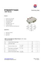
Preliminary Data IGBT Module Field Stop Trench Gate IGBT Lead Free, Compliant with RoHS Requirement High Power Converters Motor Drives IGBT, Inverter Maximum Rated Values(TC=25℃unless otherwise specified) VCES Collector-Emitter Blocking Voltage Gate-Emitter Voltage Continuous Collector Current TC = 25℃ Peak Collector Current Repetitive Short Circuit Withstand Time Maximum Power Dissipation (IGBT) www.rongtechpower.com 2018 Rongtech All rights reserved
Open the catalog to page 1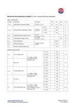
Electrical Characteristics of IGBT (TC=25℃unless otherwise specified) Static Characteristics Symbol Gate-Emitter Threshold Voltage TJ=25℃ Collector-Emitter Saturation Voltage Collector-Emitter Leakage Current Gate-Emitter Leakage Current Output Capacitance Input Capacitance Reveres Transfer Capacitance VCC=300V,IC=400A, RGoff =0Ω,VGE=±15V, Inductive Load tf Fall Time Turn-on Switching Loss VCC=300V,IC=400A, RGon =0Ω,VGE= ±15V, di/dt =1460A/μs(TJ=150℃) Inductive Load www.rongtechpower.com 2018 Rongtech All rights reserved Turn-off Delay Time Rise Time Turn-on Delay Time
Open the catalog to page 2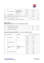
Diode, Inverter Maximum Rated Values (TC=25°Cunless otherwise specified) Vrrm www.rongtechpower.com 2018 Rongtech All rights reserved
Open the catalog to page 3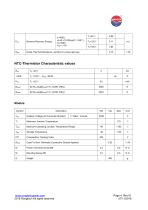
NTC-Thermistor Characteristic values R25 www.rongtechpower.com 2018 Rongtech All rights reserved
Open the catalog to page 4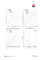
Fig.1 Typical Saturation Voltage Characteristics 800 Fig.2 Typical Output Characteristics 10 www.rongtechpower.com 2018 Rongtech All rights reserved
Open the catalog to page 5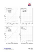
VR=300V,VGE=-15V, RGon=0ohm, Induction Load Erec Tj=125℃ Erec Tj=150℃ Fig.5 Typical Switching Loss vs. Collector Current Fig.6 Typical Switching Loss vs. Forward Current VR=300V,VGE=-15V, IF=400A Induction Load Erec Tj=125℃ Erec Tj=150℃ Fig.7 Typical Switching Loss vs. Gate Resistance www.rongtechpower.com 2018 Rongtech All rights reserved Fig.8 Typical Switching Loss vs. Gate Resistance
Open the catalog to page 6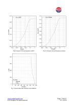
time(s) Fig.9 Transient Thermal Impedance (IGBT) Fig.10 Transient Thermal Impedance (Diode) VCES(V) Fig.11 Reverse Bias Safe Operation Area (RBSOA) www.rongtechpower.com 2018 Rongtech All rights reserved
Open the catalog to page 7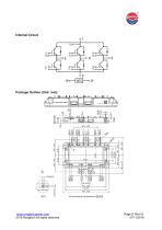
Internal Circuit Package Outline (Unit: mm): RTM400FF75A8H www.rongtechpower.com 2018 Rongtech All rights reserved
Open the catalog to page 8
Announcement Information in this document is believed to be accurate and reliable. However, Rongtech does not give any representations or warranties, expressed or implied, as to the accuracy or completeness of such information and shall have no liability for the consequences of use of such information. Right to Make Changes Rongtech reserves the right to make changes to information published in this document, including without limitation specifications and product descriptions, at any time and without notice. This document supersedes and replaces all information supplied prior to the publication...
Open the catalog to page 9All Rongtech Industry (Shanghai) Inc., catalogs and technical brochures
 RTO600/800/1000AS52 series
3 Pages
 RM110N06PK
5 Pages
 RM110N06PA
5 Pages
 RM75N08PA
5 Pages
 RM70N06PA
5 Pages
 RM60N10PA
5 Pages
 RM50N06PA
5 Pages
 RM45N06PA
5 Pages
 RM40N10PK
5 Pages
 RM40N10PA
5 Pages
 RM30N20PK
5 Pages
 RM20N10PA
5 Pages
 RVS47N60PN
11 Pages
 RTU400SG120FA2
7 Pages
 RTU600SG120FA2
7 Pages
 RTU300HF120FA2
7 Pages
 RTU200HF120FA2
7 Pages
 RTU150HF120FA2
7 Pages
 RTU100HF120FA1
7 Pages
 RTU75HF120FA1
7 Pages
 RTU50HF120FA1
7 Pages
 RTU40HF120FA1
7 Pages
 RTK600SG120B
7 Pages
 RTK400SG120B
7 Pages
 RTK300HF120B
7 Pages
 RTK200HF120B
7 Pages
 "RT25PI120B9H" IGBT Module
13 Pages
 RFR60F30APN
3 Pages
 RFR30F60PN
3 Pages
 RFR30F40PN
3 Pages
 RFM200CC4A2D
3 Pages
 RTVSM100 series
3 Pages
 RTVS4000 series
2 Pages
 RTV25-1000 series
2 Pages
 RTV025A series
2 Pages
 RTO20000HB series
2 Pages
 RTO5000HAX series
2 Pages
 RTO3000HT
2 Pages
 RTO2000K series
2 Pages
 RT0300LB series
2 Pages
 RTO200G3 series
2 Pages
 RTO1000DHR series
2 Pages
 RTO800,1200,1500BHS52 series
3 Pages
 RTO900HC5F series
3 Pages
 RTO600/800/900TF512 series
2 Pages
 RTO500K1 series
2 Pages
 RTO500E series
2 Pages
 RTO600B series
2 Pages
 RTNT1000-C3 series
2 Pages
 RTLT1000/2000SH series
2 Pages
 RTLT1000SH series
2 Pages
 RTC500LTB series
2 Pages
 RTC300TAH series
2 Pages
 RTC100LTA
2 Pages
 RTC200P3
2 Pages
 RTC200LP series
2 Pages
 RTC50LA2
2 Pages
 RTC50Q58 series
2 Pages
 RTC200ECH Series
2 Pages
 RTC100LAH sereies
2 Pages
 RTC50LSRTC50LS
2 Pages
 RTC035A series
2 Pages
 RTC25DT52
2 Pages
 RT40PI120T5H PIM module
10 Pages
 RT25PI120B9H PIM module
11 Pages
 RT10PI120B3H PIM module
7 Pages
 RTM800FF65HP2S IGBT module
10 Pages
 RTR600HF170T9H IGBT module
8 Pages
 RTS600HF120T9H IGBT Module
8 Pages
 RTM400FF120B8S IGBT Module
10 Pages
 RT100PI120T6H-M IGBT module
14 Pages
 RTV25-1000 voltage sensor
2 Pages
 RTV025A voltage sensor
2 Pages
 RTLT1000SH current sensor
2 Pages
 RTNT400-S current sensor
2 Pages
 RTC200ECH current sensor
2 Pages
 RTC100LAH current sensor
2 Pages
 RTC75LX current sensor
2 Pages
 RTC050A current sensor
2 Pages
 RH701 current IC senser
41 Pages
 RTC050DT52 current sensor
2 Pages
 RTC050H5 SERIES
2 Pages
 GT300HF120T2VH IGBT module
6 Pages


Archived catalogs
 RTC06H5
3 Pages
 GT100FF120T6H IGBT module
7 Pages
 GT100HF120T1VH IGBT module
7 Pages


- Power supply unit
- DC power supply
- AC/DC power supply
- Capacitor
- Battery charger
- Current sensor
- Single-phase power supply
- Lead battery charger
- AC current sensor
- Ceramic capacitor
- Transistor module
- DC current sensor
- Automatic battery charger
- SMD capacitor
- Power capacitor
- Lead-acid battery charger
- Mobile battery charger
- Film capacitor
- Rectifier diode