- Catalogs
- Rongtech Industry (Shanghai) Inc.,
- RT40PI120T5H PIM module
RT40PI120T5H PIM module
1 /10Pages

RT40PI120T5H PIM module
1 /10Pages
Catalog excerpts
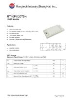
Features: Short Circuit Rated 10μs Low Saturation Voltage: VCE (sat) = 1.90V @ IC = 40A , TC=25℃ Low Switching Loss 100% RBSOA Tested(2×Ic) Low Stray Inductance Lead Free, Compliant with RoHS Requirement Applications: Industrial Inverters Servo Applications IGBT, Inverter Maximum Rated Values (TC=25℃Unless otherwise specified) VCES Collector-Emitter Blocking Voltage Gate-Emitter Voltage Continuous Collector Current TC = 25℃ Peak Collector Current Repetitive Short Circuit Withstand Time Maximum Power Dissipation per IGBT
Open the catalog to page 1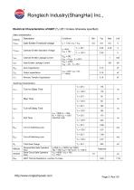
Rongtech Industry(ShangHai) Inc., Electrical Characteristics of IGBT (TC=25℃Unless otherwise specified) Static characteristics Gate-Emitter Threshold Voltage Collector-Emitter Saturation Voltage Collector-Emitter Leakage Current Gate-Emitter Leakage Current Input Capacitance Output capacitance Reverse Transfer Capacitance Turn-off Switching Loss Turn-on Switching Loss Fall Time Turn-off Delay Time Rise Time Turn-on Delay Time Total Gate Charge RBSOA SCSOA RθJC Reverse Bias Safe Operation Area Short Circuit Safe Operation Area IGBT Thermal Resistance: Junction-To-Case
Open the catalog to page 2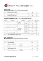
Rongtech Industry(ShangHai) Diode, Inverter Maximum Rated Values (Tc=25°C Unless otherwise specified)
Open the catalog to page 3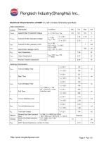
Rongtech Industry(ShangHai) IncElectrical Characteristics of IGBT (TC=25°C Unless otherwise specified) Static characteristics Http://www.rongte c hpowe r.com
Open the catalog to page 4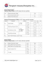
Rongtech Industry(ShangHai) IncDiode, Brake-Chopper Maximum Rated Values (Tc=25°C Unless otherwise specified) Vrrm
Open the catalog to page 5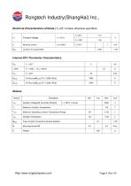
Rongtech Industry(ShangHai) Inc Electrical Characteristics of Diode (TC=25°C Unless otherwise specified)Internal NTC-Thermistor Characteristics 25 Http://www.ro ngte c hpowe r.com
Open the catalog to page 6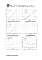
Fig.1 Typical Saturation Voltage Characteristics Fig.2 Typical Output Characteristics Cies Coes Fig.5 Typical Switching Loss vs. Collector Current Fig.6 Typical Switching Loss vs. Gate Resistance
Open the catalog to page 7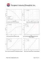
Load Current(A) Fig.7 Typical Load Current vs. Frequency Fig.8 Transient thermal impedance (IGBT) Fig.9 Transient thermal impedance Diode Fig.10 Typical Saturation Voltage Characteristics (Brake-Chopper) Fig.11 Forward Characteristics of FWD (Brake-Chopper) Fig.12 Forward Characteristics of Diode (Rectifier)
Open the catalog to page 8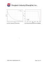
Rongtech Industry(ShangHai) Inc., 10 Rtyp Module Chip Fig.14 Reverse Bias Safe Operation Area (RBSOA)
Open the catalog to page 9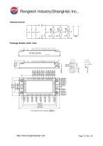
Rongtech Industry(ShangHai) Inc., Internal Circuit: Package Outline (Unit: mm):
Open the catalog to page 10All Rongtech Industry (Shanghai) Inc., catalogs and technical brochures
 RTO600/800/1000AS52 series
3 Pages
 RM110N06PK
5 Pages
 RM110N06PA
5 Pages
 RM75N08PA
5 Pages
 RM70N06PA
5 Pages
 RM60N10PA
5 Pages
 RM50N06PA
5 Pages
 RM45N06PA
5 Pages
 RM40N10PK
5 Pages
 RM40N10PA
5 Pages
 RM30N20PK
5 Pages
 RM20N10PA
5 Pages
 RVS47N60PN
11 Pages
 RTU400SG120FA2
7 Pages
 RTU600SG120FA2
7 Pages
 RTU300HF120FA2
7 Pages
 RTU200HF120FA2
7 Pages
 RTU150HF120FA2
7 Pages
 RTU100HF120FA1
7 Pages
 RTU75HF120FA1
7 Pages
 RTU50HF120FA1
7 Pages
 RTU40HF120FA1
7 Pages
 RTK600SG120B
7 Pages
 RTK400SG120B
7 Pages
 RTK300HF120B
7 Pages
 RTK200HF120B
7 Pages
 "RT25PI120B9H" IGBT Module
13 Pages
 RFR60F30APN
3 Pages
 RFR30F60PN
3 Pages
 RFR30F40PN
3 Pages
 RFM200CC4A2D
3 Pages
 RTVSM100 series
3 Pages
 RTVS4000 series
2 Pages
 RTV25-1000 series
2 Pages
 RTV025A series
2 Pages
 RTO20000HB series
2 Pages
 RTO5000HAX series
2 Pages
 RTO3000HT
2 Pages
 RTO2000K series
2 Pages
 RT0300LB series
2 Pages
 RTO200G3 series
2 Pages
 RTO1000DHR series
2 Pages
 RTO800,1200,1500BHS52 series
3 Pages
 RTO900HC5F series
3 Pages
 RTO600/800/900TF512 series
2 Pages
 RTO500K1 series
2 Pages
 RTO500E series
2 Pages
 RTO600B series
2 Pages
 RTNT1000-C3 series
2 Pages
 RTLT1000/2000SH series
2 Pages
 RTLT1000SH series
2 Pages
 RTC500LTB series
2 Pages
 RTC300TAH series
2 Pages
 RTC100LTA
2 Pages
 RTC200P3
2 Pages
 RTC200LP series
2 Pages
 RTC50LA2
2 Pages
 RTC50Q58 series
2 Pages
 RTC200ECH Series
2 Pages
 RTC100LAH sereies
2 Pages
 RTC50LSRTC50LS
2 Pages
 RTC035A series
2 Pages
 RTC25DT52
2 Pages
 RT25PI120B9H PIM module
11 Pages
 RT10PI120B3H PIM module
7 Pages
 RTM800FF65HP2S IGBT module
10 Pages
 RTR600HF170T9H IGBT module
8 Pages
 RTS600HF120T9H IGBT Module
8 Pages
 RTM400FF120B8S IGBT Module
10 Pages
 RTM400FF75A8H IGBT Module
9 Pages
 RT100PI120T6H-M IGBT module
14 Pages
 RTV25-1000 voltage sensor
2 Pages
 RTV025A voltage sensor
2 Pages
 RTLT1000SH current sensor
2 Pages
 RTNT400-S current sensor
2 Pages
 RTC200ECH current sensor
2 Pages
 RTC100LAH current sensor
2 Pages
 RTC75LX current sensor
2 Pages
 RTC050A current sensor
2 Pages
 RH701 current IC senser
41 Pages
 RTC050DT52 current sensor
2 Pages
 RTC050H5 SERIES
2 Pages
 GT300HF120T2VH IGBT module
6 Pages


Archived catalogs
 RTC06H5
3 Pages
 GT100FF120T6H IGBT module
7 Pages
 GT100HF120T1VH IGBT module
7 Pages


- Power supply unit
- DC power supply
- AC/DC power supply
- Capacitor
- Battery charger
- Current sensor
- Single-phase power supply
- Lead battery charger
- AC current sensor
- Ceramic capacitor
- Transistor module
- DC current sensor
- Automatic battery charger
- SMD capacitor
- Power capacitor
- Lead-acid battery charger
- Mobile battery charger
- Film capacitor
- Rectifier diode