- Catalogs
- Romutec Steuer- u. Regelsysteme GmbH
- K2 _MXBUS-tec

- Products
- Catalogs
- News & Trends
- Exhibitions
K2 _MXBUS-tec
K2 _MXBUS-tec
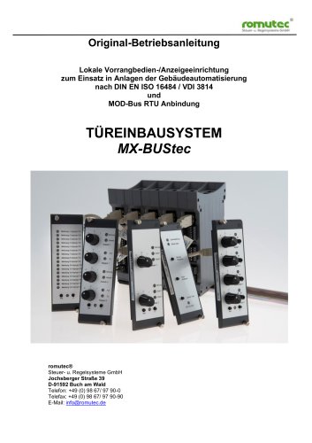
The MX-BUStec system by romutec provides a clear display of system status, emergency operation capabilities, and integration with DDC substations via MODBus. It includes manual operation with emergency functions and fault signaling compliant with DIN VDI 3814. Designed for easy installation in a 19" rack, it optimizes control cabinet size and allows operation by non-electrical personnel. It supports direct connection to MOD-BUS RTU as slave devices and features automatic baud rate detection.
This manual is for trained electrical professionals familiar with electrical switchgear installation and commissioning. It should be stored with wiring diagrams and transferred with the product if sold.
Read safety instructions before use. The MX-BUStec is for controlling actuators in HVAC systems and should be used as specified. Avoid installation near frequency converters and ensure compliance with protective measures. Only authorized personnel should perform wiring, and the device should not be operated near water.
Devices should be used as intended and maintained properly. The manual must be available on-site, and only trained personnel should operate the devices. Installation and maintenance should be performed by professionals. Contact the manufacturer for malfunctions instead of attempting repairs.
The MX-BUStec is a manual control level with emergency function in 19" rack technology. It consists of remote I/O modules and 19" modules installed in a control cabinet door. Communication with MODBus Master devices is via RS485 using MODBus RTU protocol. It replaces traditional switches and allows for cost-effective bus wiring. Each module has its own RS485 bus interface, eliminating the need for a gateway module. The address is set using a 16-position rotary coding switch. The system can operate more than 16 modules on a bus, except for the lamp test module, which can only appear once.
Hardware
Each module receives an address between 0 and 15 via a rotary coding switch, except for the lamp test module. Up to 65 expansion modules can be connected to a MODBus interface. Modules are mounted and wired in the control cabinet on the mounting plate. Modules in the control cabinet door are connected via USB cables, which also supply power.
Bus Connection to MODBus Master Devices
Communication requires configuring an interface as a MODBus master using the manufacturer's programming software. Terminal assignment for the MODBus RTU (RS485) connection is specified, and termination of the RS485 interface is required.
The system supports Read Holding Registers, Write Single Register, and Write Multiple Registers, with limitations on the number of registers that can be read or written in a single command.
Options include controlling door module LEDs via bus command or terminals, activating fault memory for digital inputs, and setting relay control via bus command or terminals. Configuration also includes options for sensor types for analog inputs and inversion of digital inputs.
Lamp Test/Central Module MBZ1030
The MBZ1030 module performs functions such as lamp testing of all connected expansion modules, signaling system-wide faults, providing a potential-free relay contact for an external horn, and switching between slave and master modes based on bus communication status.
- Power Supply: +24 V DC, 220 mA current consumption.
- Analog Outputs: 4 outputs, 0-10V, 10 mA load capacity, short-circuit proof.
- Analog Inputs: Configurable for 0-10V, 0-20mA, and various resistance sensors.
- Resolution: 8-bit for AO, 10-bit for AI.
- Linear Error: Less than +/- 2%.
- Labeling: Customizable laser-engraved labels are available, with options for post-installation ordering.
- Mounting Frames: Various frames are available for installing multiple control cards, with specifications for dimensions and mounting methods.
- Power Supplies: Compact power supplies for the control cards, with specifications for input voltage, output voltage, and current.
- Operating Temperature: 0-50°C.
- Storage Temperature: 0-70°C.
- Humidity: 10-90%, non-condensing.
- Protection Class: IP20, up to IP54 with additional covers.
This document outlines the configuration and operation of digital inputs, outputs, and LED indicators for a control and regulation system by Romutec Steuer.-und Regelsysteme GmbH. It includes detailed hexadecimal values for various operations and configurations.
The document specifies the digital inputs (DI) for two drives, including automatic operation, operational messages, and error messages. Each DI is associated with a specific hexadecimal value for configuration. The document also details the inversion of digital inputs, which affects LED indicators when controlled via terminals.
LEDs are controlled via MODBus commands or terminal connections. Each LED can be set to red or green, and the document provides hexadecimal values for these settings. The LEDs can also be configured to blink for error messages until acknowledged.
Switches and buttons are configured with specific hexadecimal values for operations such as automatic mode, off, and stage settings. The document provides values for querying the status of these controls.
Switching times for drive stages are specified in milliseconds, with values provided for both upward and downward transitions between stages.
The document includes MODBus addresses for various modules, with specific instructions for setting these addresses using rotary switches.
The document describes the configuration of an analog output module with four outputs ranging from 0 to 10 volts. It includes MODBus addressing and control settings for these outputs.
Error messages and status updates are stored and managed through specific configurations, with hexadecimal values provided for each digital input.
The document details the functional selection for follow-up outputs, which can be controlled via MODBus or based on the status of digital inputs.
The document includes technical notes and disclaimers about potential changes and the current version of the document.
Each analog output (AO) is controlled based on its corresponding analog input (AI) with a range of 0 to 10V. The configuration is represented in hexadecimal values for each AO.
Various registers (R111, R800, R810, etc.) are used to control and read analog outputs and inputs via MODBus. The values are represented in both hexadecimal and decimal, where 0xFF or D 255 corresponds to 10 volts.
Register R1120 allows selection of sensor types for analog inputs, including voltage, current, resistance, and specific temperature sensors like PT 100 and Ni 1000.
Registers such as R300 and R301 manage digital inputs, including inversion options. R3200 handles button and switch states, with specific bits indicating different actions.
Registers like R51, R55, and R101 manage the operation of LEDs and buzzers on the door module, with specific configurations for master mode and error signaling.
Relay operations are managed through registers like R110 and R57, allowing for logical OR operations to control multiple relays simultaneously.
Registers R90 and R3 configure baud rate settings, with options for automatic detection or fixed rates. R5 allows sending commands to the module, such as lamp tests and resets.
Registers R0, R1, R3000, and R3001 provide information on module types and firmware versions, with values encoded in hexadecimal.
Catalog excerpts
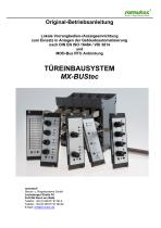
Original-Betriebsanleitung Lokale Vorrangbedien-/Anzeigeeinrichtung zum Einsatz in Anlagen der Gebäudeautomatisierung nach DIN EN ISO 16484 / VDI 3814 und MOD-Bus RTU Anbindung TÜREINBAUSYSTEM MX-BUStec romutec® Steuer- u. Regelsysteme GmbH Jochsberger Straße 39 D-91592 Buch am Wald Telefon: +49 (0) 98 67/ 97 90-0 Telefax: +49 (0) 98 67/ 97 90-90 E-Mail: [email protected]
Open the catalog to page 1
romutec Steuer.-und Regelsysteme GmbH Jochsberger Straße 39 Technische Änderungen vorbehalten
Open the catalog to page 2
Stcuer- u. Regelsysteme GmbH Lokale Vorrangbedien-/Anzeigeeinrichtung mit integriertem Stormeldesystem Dies bietet die LVB mit Tureinbaumodulen MX-BUStec von romutec®: • Ubersichtliche Anordnung und Darstellung des Anlagenzustandes • Notbedienung bzw. Handeingriff jederzeit moglich • Verbindung zwischen Tureinbausystem und DDC-Unterstation nach MODBus Spezifikation • Handbedienebene mit Notfunktion und Stormeldesystem (nach DIN VDI 3814) • Einfache Verdrahtung auf der Montageplatte, steckbare Verbindungen zu den Bedien- und Anzeigemodulen im genormten 19“-Tragerrahmen in der Schaltschrankture...
Open the catalog to page 3
2. Hinweise zur Bedienungsanleitung Um alle Vorteile Ihrer neuen Handbedienebene umfassend nutzen zu können, sollten Sie alle Kapitel dieser Bedienungsanleitung lesen, um die Merkmale der Geräte kennenzulernen und den sicheren Umgang mit dem System zu erlernen. 2.1 Zielgruppe(n) und Personalqualifikation Diese Betriebsanleitung richtet sich an ausgebildete Elektro-Fachkräfte, die mit der Installation und der Inbetriebnahme von elektrischen Schaltanlagen vertraut sind. Weiterhin richtet sich diese Betriebsanleitung an Planer und Bediener der Anlagen, in welche die Geräte eingebaut werden/sind....
Open the catalog to page 4
Stcuer- u. Rcgelsysteme GmbH • Beachten Sie alle am Gerat angebrachten oder in der technischen Dokumentation aufgefuhrten Hinweise und Warnungen. • Betreiben Sie das Gerat nur in den dafur vorgesehenen Halterungen oder Einbaurahmen Fuhren Sie keine Verdrahtungsarbeiten unter Spannung durch. Es besteht die Gefahr eines elektrischen Schlags, da einige Klemmen 230 V fuhren konnen. Das Verbinden und Losen von Steckverbindungen unter Spannung ist zu vermeiden. Hierbei besteht ebenfalls die Gefahr eines elektrischen Schlages. • Die Module sollten nicht in unmittelbarer Umgebung von Frequenzumrichtern...
Open the catalog to page 5
4. Systembeschreibung MX-BUStec ist eine romutec®-Handbedienebene mit Notfunktion in 19“- Einbautechnik. Diese besteht aus den abgesetzten I-/O-Modulen auf der Hutschiene (Rail) und den 19“-Modulen (Front), die in einem Trägerrahmen in die Schaltschranktüre eingebaut werden. Die Anbindung an die MODBus Master Geräte erfolgt über eine RS485 Verbindung. Die Kommunikation erfolgt dabei über MODBus RTU. Funktional ersetzt die romutec®-Handbedienebene herkömmliche Schalter und Meldeleuchten, Störmeldesysteme und Koppelrelais etc. in konventionellen Schaltschränken. An die Stelle von kostenintensiven...
Open the catalog to page 6
5. Konfiguration 5.1 Hardware Maximale Anzahl der Erweiterungsmodule pro MODBus-Schnittstelle Durch einen Drehcodierschalter erhält jedes Modul eine Adresse zwischen 0 und 15, mit Ausnahme des Lampentestmoduls, dessen Adresse nicht einstellbar ist. Da sich die verschiedenen Modultypen zusätzlich intern über einen Adress-Offset unterscheiden, können an einer MODBus-Schnittstelle des Master Gerätes theoretisch bis zu 65 Erweiterungsmodule angeschlossen werden. Diese Zahl ergibt sich aus 4 Modultypen (MLM1010, MDH1010, MDH1210, MAH1010) mal 16 möglichen Adressen pro Typ plus 1x MBZ1010. Bitte beachten...
Open the catalog to page 7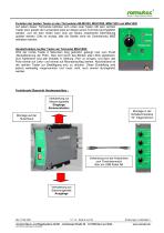
Funktion der beiden Taster an den Türmodulen MLM1020, MDH1020, MDH1220 und MAH1020 Auf jedem dieser Türmodule befinden sich unten zwei Taster. Mit dem rechten Taster kann jeweils der Lampentest lokal an diesem einen Türmodul durchgeführt werden, und mit dem linken kann eine am Modul anstehende Störmeldung quittiert werden. Dies ist wichtig, falls die Geräte ohne ein Zentralmodul MBZ betrieben werden. Sonderfunktion rechter Taster am Türmodul MAH1020: Wird der rechte Taster 8 Sekunden lang gedrückt, gelangt man zum Punkt „Neukalibrierung der Potis“. Dies wird durch das Blinken aller LEDs signalisiert....
Open the catalog to page 8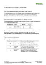
Stcuer- u. Rcgelsysteme GmbH 5.2 Busanbindung an MODBus Master Gerate5.2.1 Kommunikation zwischen MODBus Master Gerate-Systemen Fur die Kommunikation zwischen MODBus Master Gerate-Systemen ist es zwingend erforderlich, eine Schnittstelle als MODBus-Master fur die Kommunikation mit der romutec®-Handbedienebene zu konfigurieren. Dies erfolgt mit der Programmiersoftware des jeweiligen Herstellers des Gerates. Bei Fragen sehen Sie im Handbuch nach oder wenden sich direkt an den Hersteller des Gerates. Die Klemmenbelegung fur die Busanbindung der Gerateserie MX-BUStec an die MODBus Master Gerate ist...
Open the catalog to page 9
5.3 Konfigurations-Register Auswahl: Ansteuerung der Türmodul-LEDs über Bus-Befehl oder Klemmen Standardmäßig werden die LEDs auf den Türmodulen in Abhängigkeit von der Ansteuerung der HardwareEingänge von den Railmodulen angesteuert. Sollen die LEDs stattdessen über Busbefehle softwaremäßig vom MODBus angesteuert werden, so ist dies vorher als „Maske“ in einem Konfigurationsregister festzulegen („Betriebsart-Vorwahl für die Türmodul-LEDs“). Beim Analogmodul MAH1010/1030 signalisieren die Türmodul-LEDs die Höhe der eingestellten analogen Ausgangsspannung. Auswahl: LED-Farbe bei Ansteuerung der...
Open the catalog to page 10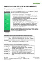
Stcuef- u. Rcgelsysteme GmbH Das Lampentestmodul MBZ1030 (bestehend aus je einem MBZ1010 und MBZ1020) ubernimmt je nach Konfiguration folgende Funktionen: • Lampentest aller angeschlossenen Erweiterungsmodule • Moglichkeit der Signalisierung einer im System gebildeten Sammelstorung mittels einer uber den MODBus anzusteuernden LED am Turmodul (Verwendung von LED 1 hierfur empfohlen, da diese beim autarken Betrieb ohne Master fest als Sammelstormeldung belegt ist) • Potentialfreier Relaiskontakt (SchlieGer) fur Anschluss einer externen Hupe • Quittierung und Entsperren von Storungen • Uberwachung...
Open the catalog to page 11All Romutec Steuer- u. Regelsysteme GmbH catalogs and technical brochures
 K1 _Bustec Mod
61 Pages
 E10_FE
5 Pages
 K1 _MOD Bus Flyer
2 Pages