- Catalogs
- Romutec Steuer- u. Regelsysteme GmbH
- K1 _Bustec Mod

- Products
- Catalogs
- News & Trends
- Exhibitions
K1 _Bustec Mod
K1 _Bustec Mod
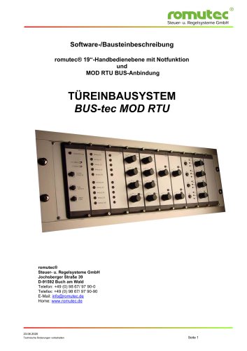
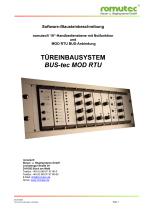
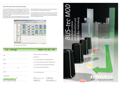
This document serves as a comprehensive guide for the romutec® 19" manual control level, featuring an emergency function and MOD RTU BUS connection. It is crucial to read all sections to fully leverage the device's capabilities and ensure safe operation.
Key safety measures include:
- Adhering to all warnings and instructions provided.
- Operating the device only in specified mounts or frames.
- Avoiding installation near frequency converters and transformers.
- Ensuring the connection voltage aligns with documentation specifications.
- Restricting wiring tasks to authorized personnel.
- Avoiding wiring under voltage to prevent electric shock and device damage.
- Preventing foreign objects from entering the device.
- Avoiding installation in areas with extreme temperature fluctuations.
The system uses the Modbus protocol via an RS485 interface, supporting multiple manual control levels with distinct station addresses on the same bus. Key settings include:
- Data bits: 8
- Stop bits: 1
- Parity: none
- Handshake: off
Each central module can connect up to 9 expansion modules, with a maximum of 8 digital or 7 analog modules. Addressing is set using jumpers, ranging from 0 to 7. Default settings can be modified via module buttons or Modbus communication.
Modules are mounted on 19" racks, with bus connections made via plug-in connections. Digital modules receive power through these connections, while analog modules require direct terminal connections.
Addressing is vital for communication, with no duplicate addresses allowed per BZK line. Digital and analog modules can share jumper addresses due to an internal address bit distinction.
Factory default settings allow immediate operation but can be changed if multiple control levels are on one bus. Configuration can be done via module buttons or Modbus communication.
A green LED indicates the configured interface type (RS485 or RS232) through blinking frequencies.
Modbus communication uses standard elements (Input, Coil, Word) with three addressing options:
- Digital I/O addressing via bit functions.
- Digital I/O addressing via word functions.
- Individual data point addressing across modules.
The document outlines technical specifications and configurations for the BZK1000MOD module, facilitating communication between romutec's manual control level and various PLC systems using the MOD-RTU protocol. It supports up to 8 digital or analog modules, with a maximum of 9 expansion modules.
- Establishing bus communication between PLC and manual control level.
- Monitoring and status display of bus communication (I2C and MOD-BUS).
- Lamp test for all connected expansion modules.
- Signaling system-wide faults using a blinking red LED and a potential-free relay contact.
- Acknowledging and unlocking external faults without storage.
- Power supply for connected digital expansion modules.
- LED I2C: Off indicates no data exchange; short blink (50 msec) indicates data exchange over I2C-Bus; long blink (300 msec) indicates module absence or illegal parameters.
- LED MOD-BUS: Slow blinking indicates readiness; short blink (100 msec) during telegram transmission when the station number is addressed.
- Addressing and cross-module data point query using word functions.
- Control of multiple LEDs/relays through binary OR of relevant bits.
- Configuration parameters include station number, baud rate, mode (Modbus RTU), and interface (RS485).
- All four parameters must be written with a single command even if only one value changes.
- Station number range: 0-249.
- Baud rates: 9600, 19200, 38400.
- Mode: Modbus RTU.
- Interface: RS485.
- Bus activity monitoring time in seconds.
The document emphasizes the necessity of writing all configuration parameters together, even if only one is altered, to ensure proper system functionality.
The BDH4800-102 module is a button-lamp card featuring 4 debounced buttons, each associated with two LEDs. LED 1 is yellow and continuously lit without triggering a collective fault, while LED 2 is red with the same behavior. Control information for LEDs 1-8 is transmitted via network input variables (nvi) bytes 2-9 to the control card. Button presses are communicated through network output variables (nvo) to the LON node, with nvo bytes 2-5 indicating button status (00 for pressed, 01 for not pressed).
Power Supply: +24 V DC via 8-pin system bus, with a voltage tolerance of ±10%. Maximum current consumption is 155mA. Operating temperature ranges from 0 to 50°C, while storage and transport temperatures range from -20 to +70°C. The module supports a relative humidity of 5-95% non-condensing. It has an IP 40 protection rating, which can be increased to IP 54 with a cover and viewing window. Dimensions are specified for 19" devices with a width of 8 TE (40.5 mm), height of 3 HE (129 mm), and installation depth of less than 80 mm. The module is designed for mounting in a 19-inch frame.
The module complies with CE standards, including EN 61000-4-2 / IEC 801-2 for electrostatic discharge (ESD) with contact and air discharge at 8 kV. It also meets EN 61000-4-5 / IEC 801-5 surge testing standards with AC supply at 4 kV, DC at 0.5 kV, and signal lines at 2 kV. Additionally, it adheres to EN 61000-4-4 / IEC 801-4 burst testing standards with inputs and outputs at ±2 kV and supply voltage AC/DC at ±2 kV.
The module can be used in combination with the BZK1000MOD (Modbus RTU). General guidelines for the romutec-LON module system should be followed regarding system configuration and module addressing.
Catalog excerpts
Steuer- u. Regelsysteme GmbH Steuer- u. Regelsysteme GmbH Jochsberger Strafte 39 D-91592 Buch am Wald Technische Anderungen vorbehalten
Open the catalog to page 1
Allgemeine Information Hinweise zur Bedienungsanleitung Um alle Vorteile Ihrer neuen Handbedienebene umfassend nutzen zu können, sollten Sie alle Kapitel dieser Bedienungsanleitung lesen, um die Merkmale der Geräte kennenzulernen und den sicheren Umgang mit dem System zu erlernen. Sicherheitshinweise Bevor Sie Ihr Gerät benutzen, sollten Sie die folgenden Sicherheitshinweise sorgfältig lesen. Dies gilt auch, falls zu einem späteren Zeitpunkt Fragen auftreten sollten. Bestimmungsgemäße Verwendung: Das Gerät ist ausschließlich für die in dieser Dokumentation vorgegebenen Bestimmungen und Leistungsmerkmale...
Open the catalog to page 2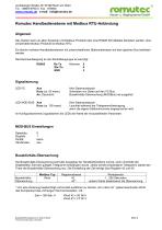
Jochsberger StraGe 39, 91592 Buch am Wald Tel. : 09867/9790-0 Fax : 979090 www.romutec.de e-mail: [email protected] Steuer- u. Regelsysteme GmbH Romutec Handbedienebene mit Modbus RTU-Anbindung Allgemein Das System kann an alien Systemen mit Modbus-Protokoll uber eine RS485 Schnittstelle betrieben werden. Das verwendete Modbus Protokoll ist Modbus RTU. Es konnen mehrere Handbedienebenen mit unterschiedlichen Stationsadressen auf dem gleichen Bus betrieben werden. Die Klemmenbelegung an der Zentralbaugruppe ist wie folgt: RS485 Rx-Tx Klemme: 5 /Rx-/Tx 4 Kurz (ca. 50 msec) An, Dauerlicht Kein Datenaustausch...
Open the catalog to page 3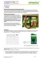
Steuer- u. Regelsysteme GmbH Jochsberger StraGe 39, 91592 Buch am Wald Tel. : 09867/9790-0 Fax : 979090 www.romutec.de e-mail: [email protected] An ein Zentral-/Kommunikationsmodul BZK1000MOD konnen bis zu 9 Erweiterungsmodule angeschlossen werden, wobei die maximale Anzahl von 8 digitalen oder 7 analogen Modulen gleichzeitig nicht uberschritten werden darf. Jede Kombination ist moglich, bezuglich der Einbaureihenfolge gibt es keine Einschrankungen. Es sind lediglich die Regeln fur die Adressierung (siehe unten) zu beachten. Montage und Busverbindungen Fur die Montage der Steuerkarten stehen 19“-Bau-gruppentrager...
Open the catalog to page 4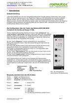
Steuer- u. Regelsysteme GmbH Jochsberger StraGe 39, 91592 Buch am Wald Tel. : 09867/9790-0 Fax : 979090 www.romutec.de e-mail: [email protected] Jedes BZK1000MOD wird mit einer werksseitig konfigurierten Defaulteinstellung (Werte siehe unten) ausge-liefert, mit der die Inbetriebnahme in der Regel sofort moglich ist. Die Defaultwerte konnen jedoch jederzeit geandert werden, was z.B. notig ist, wenn mehrere romutec®-Handbedienebenen (mit unterschiedlichen Stationsnummern) an einem Bus betrieben werden sollen. Zum Andern der Defaultwerte stehen zwei Wege zur Verfugung, namlich einerseits die Anderung...
Open the catalog to page 5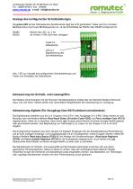
Jochsberger Straße 39, 91592 Buch am Wald Tel. : 09867/9790-0 Fax : 979090 www.romutec.de e-mail: [email protected] Anzeige des konfigurierten Schnittstellentyps Die grüne LED auf der Rückseite des Zentralmoduls zeigt bei nicht gedrücktem Taster auch im normalen Betriebsmodus durch zwei Blinkfrequenzen an, ob die Schnittstelle als RS232 oder RS485 konfiguriert ist: RS485 RS232 Blinken der LED, ca. 2 Hz ab Version V108 nicht mehr verfügbar Taster für Defaultwerte LED zur Signalisierung des Schnittstellentyps Abb.: LED zur Anzeige des konfigurierten Schnittstellentyps und Taster zum Einstellen der...
Open the catalog to page 6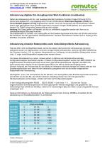
Jochsberger Straße 39, 91592 Buch am Wald Tel. : 09867/9790-0 Fax : 979090 www.romutec.de e-mail: [email protected] Adressierung digitaler Ein-/Ausgänge über Wort-Funktionen (modulweise) Neben der Adressierung der Ein- und Ausgänge über Bit-Funktionen (Function Codes FC02 und FC15) können alle digitalen Ein- und Ausgänge auch mit den Wortfunktionen Read Input Registers (FC04) bzw. Force Multiple Registers (FC16) angesprochen werden. Auch bei Verwendung der Wortfunktionen müssen jedoch stets alle Register eines Erweiterungsmoduls mit einem einzigen Befehl gelesen bzw. geschrieben werden. Ein Zugriff...
Open the catalog to page 7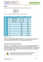
Steuer- u. Regelsysteme GmbH Jochsberger StraGe 39, 91592 Buch am Wald Tel. : 09867/9790-0 Fax : 979090 www.romutec.de e-mail: [email protected] Ein BZK1000 MOD soil mit den aufgefuhrten Erweiterungsmodulen betrieben werden: Dann sind in die Konfigurationsregister die folgenden Werte einzutragen: Hinweis: Fur die Berechnung der Datenpunkt-Adressen aus den im Anhang befindlichen Cross-Listen ist nach der Konfiguration der Register R2000 ... R2015 nur noch der Indexentscheidend, nicht mehr die gejumperte Moduladresse, da diese nun ja in den Konfigurationsregistern enthalten ist. Ab der Version 3.121...
Open the catalog to page 8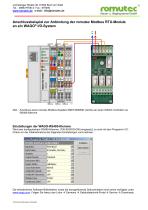
Jochsberger Straße 39, 91592 Buch am Wald Tel. : 09867/9790-0 Fax : 979090 www.romutec.de e-mail: [email protected] Anschlussbeispiel zur Anbindung der romutec Modbus RTU-Module an ein WAGO® I/O-System Abb.: Anschluss eines romutec Modbus-Kopplers BZK1000MOD (rechts) an einen WAGO-Controller via RS485-Klemme Einstellungen der WAGO-RS485-Klemme Wird eine konfigurierbare RS485-Klemme (750-653/003-000) eingesetzt, so sind mit dem Programm I/OCheck vor der Inbetriebnahme die folgenden Einstellungen vorzunehmen: Die erforderlichen Software-Bibliotheken sowie die dazugehörende Dokumentation sind online...
Open the catalog to page 9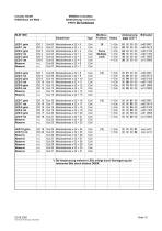
romutec GmbH 91592 Buch am Wald MODBus Crossliste, Adressierung modulweise mittels Bit-Funktionen Technische Anderungen vorbehalten
Open the catalog to page 10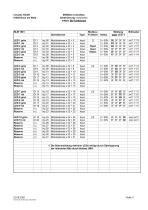
romutec GmbH 91592 Buch am Wald MODBus Crossliste, Adressierung modulweise mittels Bit-Funktionen Technische Anderungen vorbehalten
Open the catalog to page 11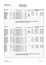
romutec GmbH 91592 Buch am Wald MODBus Crossliste, Adressierung modulweise mittels Bit-Funktionen Technische Anderungen vorbehalten
Open the catalog to page 12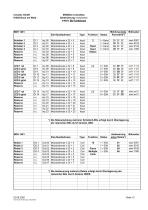
romutec GmbH 91592 Buch am Wald MODBus Crossliste, Adressierung modulweise mittels Bit-Funktionen Technische Anderungen vorbehalten
Open the catalog to page 13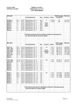
romutec GmbH 91592 Buch am Wald MODBus Crossliste, Adressierung modulweise mittels Bit-Funktionen Technische Anderungen vorbehalten
Open the catalog to page 14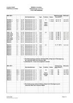
romutec GmbH 91592 Buch am Wald MODBus Crossliste, Adressierung modulweise mittels Bit-Funktionen Technische Anderungen vorbehalten
Open the catalog to page 15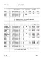
romutec GmbH 91592 Buch am Wald MODBus Crossliste, Adressierung modulweise mittels Bit-Funktionen Technische Anderungen vorbehalten
Open the catalog to page 16All Romutec Steuer- u. Regelsysteme GmbH catalogs and technical brochures
 K2 _MXBUS-tec
56 Pages
 E10_FE
5 Pages
 K1 _MOD Bus Flyer
2 Pages