Catalog excerpts

THICKNESS GAUGING
Open the catalog to page 1
The LTM Thickness Gauging Systems from ROLAND ELECTRONIC GmbH are used for the non contact measurement of various moving materials with a very high accuracy, in gm range. The combination of state-of-the-art laser and system technology in conjunction with a software developed especially for this requirement allows the acquisition, evaluation, visualization and archiving of thickness and cross-sectional measured values for your application. The systems were designed specifically for use in the metalworking industry and are used in rolling mills, longitudinal and cross-section plants, press...
Open the catalog to page 2
Basics ROLAND Thickness Gauging Systems ● Static and dynamic system ● Measuring modes ● Line measuring ● Micro – Traversing ● Macro-Traversing ● Macro – Traversing with Track Mesurement ● Principle of Thickness Gauging with Laser ● Operation range ● Measuring distance ● Measuring focus ● Unit passing line ● Structure of Thickness Gauging Systems ● Mechanics ● Material transfer system ● Control concept of LTM-ECO, LTM-BASE, LTM-SMART, LTM-MAXI ● Thickness Gauging Software LTM-S ● Measuring accuracy ● Calibration system ● Testing of mesuring ability ● Influencing variables and requirements...
Open the catalog to page 3
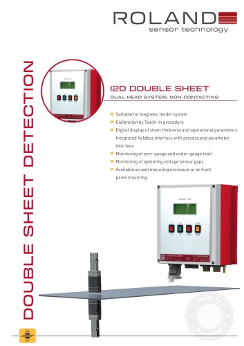
Thickness Gauging Systems Depending on the measuring tasks and the corresponding operating conditions, such as the specific installation situation and location, the required accuracy and environmental conditions you can selected from a wide range of ROLAND Thickness Gauging Systems. and Dynamic Thickness Gauging Basically, we distinguish two types of measurement systems. In the case of static measuring system (e.g. LTM-BASE), the measuring point is unchanged with respect to the system. In the case of the dynamic measuring system (e.g. LTM-SMART), the measuring point can change its position...
Open the catalog to page 4
Line Measuring ■ Macro-Traversing In the case of macro-traversing, the Y coordinate of the measuring system changes dynamically. By doing that, the system oscillates back and forth between two fixed Y coordinates (Y1 and Y2) at a constant speed. The two coordinates Y1 and Y2 result from the two edges of the current material to be measured. Only the movement of the material in the X direction produces thickness measurements along a determined sinusoidal line. It is measured over the entire strip or material width. with track measuring The macro-traversing with track measurement basically...
Open the catalog to page 5
of Thickness Gauging via Laser Triangulation The lasers used in the ROLAND Thickness Gauging Systems function according to the principle of triangulation. That means a distance determination by simple trigonometric function.A laser spot is projected onto the material surface. Depending on the distance of the material surface, the reflected laser beam meets the receiving element of the laser at a certain angle. From this angle and the fixed distance of the laser source to the receiver part, the distance of the laser to the material surface can be determined. Within ROLAND Thickness Gauging...
Open the catalog to page 6
Basics The matching line results from the reference edge of the system (Z-direction) to the measuring center point minus half the material thickness. As a measure of the material thickness, the most commonly measured nominal thickness is used. Operation range and measuring distance Measuring focus and matching line of ROLAND Thickness Gauging Systems During the development of the Roland Thickness Gauging Systems all necessary requirements in the field of mechanics and electrics were taken into account, which will result from modern production processes and the measuring technology to be...
Open the catalog to page 7
transfer system The dynamic systems LTM-SMART and LTM-MAXI are structurally designed for an upgrade with a material transfer system. This permits, if not feasible from the customers system, the necessary smooth transport of the materials, as well as the proper material guiding. Thickness Gauging System LTM-SMART with a material transfering system The control concept for the thickness gauging system LTM-ECO is based on an embedded solution. This allows a small compact design, making integration into a customer-side system very easy. All necessary components for controlling and regulating the...
Open the catalog to page 8
concept for LTM-BASE, LTM-SMART, LTM-MAXI The basic control principle for LTM-BASE, LTM-SMART and LTM-MAXI systems is based on a server-client solution. Internally, on the CPU (Beckhoff), the necessary server and the included internal client are installed. An optional 21.5“ touch monitor is used to operate the measuring system. A customer mouse and keyboard can optionally be connected via USB. Additional clients can be connected to the controller via Ethernet if required and do enable an almost open operating concept. To synchronize the determined thickness measurements with the associated...
Open the catalog to page 9
Gauging Software LTM-S The Thickness Gauging software LTM-S (internal client) is included in the scope of delivery of the Thickness Gauging Systems LTM-BASE, LTM-SMART and LTM-MAXI. LTM-S (internal client) and includes all necessary tools for the operation, processing, presentation and provision of the recorded thickness measurement values. Start screen of the Thickness Gauging Software LTM-S In addition to the simple, intuitive operation, the clear presentation of the thickness measurement values enable customers to optimally assess the dimensional thickness of the material as a function...
Open the catalog to page 10
Display of the tool „Thickness-Trend course in Y-direction/cross section“ Special attention was paid to the needs of maintenance during development. An extensive diagnostic tool allows the simplest diagnosis of the system without prior knowledge. All measurement analysis is very easy to read and intuitive. ILTM-S Vl.O © 2018 ROLAND ELECTRONIC GmbH Nominal thickness: _J Client/Server-commumcation Delayed track: □ LTM-PIC connection | Number of active tracks: Customer-PlC connecton .. | reins*?*—_= 1 Ready for operation f. . | Ready to measure Max: Display of the tool „Measuring...
Open the catalog to page 11All ROLAND ELECTRONIC catalogs and technical brochures
-
 NS9N-AAD-SC
4 Pages
-
 Angle Control Unit SIS-ACU
4 Pages
-
 SHX42 Sensor bracket
4 Pages
-
 Remote Service Box RSB
2 Pages
-
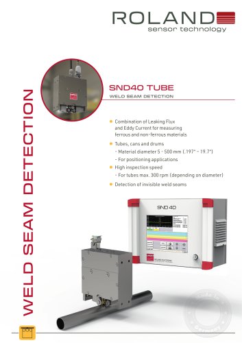 SND40 for tubes
4 Pages
-
 SND40 for coils
4 Pages
-
 ECT40
ECT404 Pages
-
 SIS Calibrator
4 Pages
-
 C100
C1004 Pages
-
 XA100
XA1004 Pages
-
 SND8S
SND8S4 Pages
-
 NS9SC
NS9SC4 Pages
-
 DOUBLE SHEET DETECTOR C100-S
4 Pages