- Catalogs
- ROHM Semiconductor
- Quasi-resonant AC/DC Converter Built-in 1700 V SiC-MOSFET
Quasi-resonant AC/DC Converter Built-in 1700 V SiC-MOSFET
1 /36Pages

Quasi-resonant AC/DC Converter Built-in 1700 V SiC-MOSFET
1 /36Pages
Catalog excerpts

Quasi-resonant AC/DC Converter Built-in 1700 V SiC-MOSFET BM2SC12xFP2-LBZ Series General Description This is the product guarantees long time support in industrial market. BM2SC12xFP2-LBZ series is a quasi-resonant AC/DC converter that provides an optimum system for all products which has an electrical outlet. Quasi-resonant operation enables soft switching and helps to keep the EMI low. This IC can be designed easily because it includes the 1700 V SiC (Silicon-Carbide) MOSFET. Design with a high degree of flexibility is achieved with current detection resistors as external devices. The burst operation reduces an electric power at light load. BM2SC12xFP2-LBZ series includes various protection functions, such as soft start function, burst operation function, over current limiter per cycle, over voltage protection, overload protection. ◼ Operating Power Supply Voltage Range: VCC: 15.0 V to 27.5 V DRAIN: 1700 V (Max) ◼ Normal Operating Current: 800 µA (Typ) ◼ Burst Operating Current: 500 µA (Typ) ◼ Maximum Operating Frequency: 120 kHz (Typ) ◼ Operating Temperature: -40 °C to +105 °C Long Time Support Product for Industrial Applications TO263-7L Package Built-in 1700 V SiC-MOSFET Quasi-resonant Type (Low EMI) Frequency Reduction Function Low Current Consumption (19 µA) during Standby Burst Operation at Light Load SOURCE Pin Leading Edge Blanking VCC UVLO (Under Voltage Lock Out) VCC OVP (Over Voltage Protection) Over Current Protection Circuit per Cycle Soft Start Function ZT Pin Trigger Mask Function ZT OVP (Over Voltage Protection) BR UVLO (Under Voltage Lock Out) FB OLP Auto Restart Latch Auto Restart Latch VCC OVP Latch Latch Auto Restart Auto Restart Applications Industrial Equipment, AC Adaptor, Household Appliances Typical Application Circuit FUSE Filter Diode Bridge SOURCE SOURCE 〇Product structure : Silicon integrated circuit www.rohm.com © 2020 ROHM Co., Ltd. All rights reserved. TSZ22111 • 14 • 001 〇This product has no designed protection against radioactive rays.
Open the catalog to page 1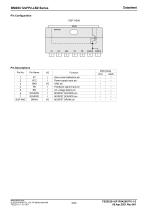
BM2SC12xFP2-LBZ Series Pin Configuration (TOP VIEW) ZT VCC GND FB BR SOURCE SOURCE DRAIN www.rohm.com © 2020 ROHM Co., Ltd. All rights reserved. TSZ22111 • 15 • 001 Function Zero current detection pin Power supply input pin GND pin Feedback signal input pin AC voltage detect pin MOSFET SOURCE pin MOSFET SOURCE pin MOSFET DRAIN pin
Open the catalog to page 2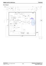
BM2SC12xFP2-LBZ Series Block Diagram VOUT Diode Bridge Internal Supply Gate Clamper Internal Supply Maximum Blanking Frequency Burst Comp. Soft Start CURRENT SENSE (V-V Change) Leading Edge Blanking www.rohm.com © 2020 ROHM Co., Ltd. All rights reserved. TSZ22111 • 15 • 001
Open the catalog to page 3
BM2SC12xFP2-LBZ Series Description of Blocks 1 Startup Sequences (FB OLP: Auto Restart Mode) The BM2SC12xFP2-LBZ’s startup sequence is shown in Figure 1. See the sections below for the detailed descriptions. Over Load Normal Load Light Load Burst Mode Switching Soft Start Figure 1. Startup Sequence Timing Chart A: B: C: The input voltage VH is applied. The VCC pin voltage rises due to start resistor RSTART. This IC starts operating when the VCC pin voltage becomes higher than VUVLO1 (Typ = 19.5 V). When the protection functions are judged as normal status, the switching operation starts. At that...
Open the catalog to page 4
Startup Sequences (FB OLP: Auto Restart Mode) – continued Start resistance RSTART is the resistance required to start the IC. If the start resistance RSTART value is set to low, the standby power becomes high and the startup time becomes short. Conversely, if the start resistance R START value is set to high, standby power becomes low and the startup time becomes long. The standby current I OFF of BM2SC12xFP2LBZ is 30 µA (Max). However, this is the minimum current required to start the IC. It is necessary to set the appropriate current value for the set target. e.g. Start Resistance RSTART Setting...
Open the catalog to page 5
BM2SC12xFP2-LBZ Series Description of Blocks – continued 2 VCC Pin Protection Function BM2SC12xFP2-LBZ includes the VCC low voltage protection function VCC UVLO and the VCC over voltage protection function VCC OVP. These functions prevent the abnormal voltage-related break in MOSFETs used for switching. The VCC UVLO function is an auto restart type comparator with voltage hysteresis and the VCC OVP function is the comparator uses latch mode or auto restart mode. After latch function is detected by VCC OVP, latching is released (reset) when the condition the VCC pin voltage < VLATCH (Typ = VUVLO2...
Open the catalog to page 6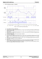
VCC Pin Protection Function – continued Figure 3. VCC UVLO/OVP (Auto Restart Mode) A: B: VH is applied, the VCC pin voltage rises. When the VCC pin voltage becomes higher than VUVLO1 (Typ = 19.5 V), the VCC UVLO function is released and the switching operation starts. C: When the VCC pin voltage becomes lower than VUVLO2 (Typ = 14.0 V), the switching operation stops by the VCC UVLO function. D: When the VCC pin voltage becomes higher than VUVLO1 (Typ = 19.5 V), the VCC UVLO function is released and the switching operation starts. E: The VCC pin voltage drops until the output voltage is stabilized....
Open the catalog to page 7
BM2SC12xFP2-LBZ Series Description of Blocks – continued 3 DC/DC Converter Function BM2SC12xFP2-LBZ uses PFM (Pulse Frequency Modulation) mode control. The FB pin, the ZT pin, and the SOURCE pin are monitored to provide a system optimized as DC/DC. The switching MOSFET ON width (turn OFF) is controlled by the FB pin and the SOURCE pin, and the OFF width (turn ON) is controlled by the ZT pin. By setting maximum frequency, PFM mode will control it to meet noise regulation. A detailed description is below. (Refer to Figure 4) Internal Supply Gate Clamper NOUT FBOLP_OH OR Maximum Blanking Frequency...
Open the catalog to page 8
DC/DC Converter Function – continued 3.1 Determination of ON Width (Turn OFF) ON width is controlled by the FB pin and the SOURCE pin. The ON width is determined by comparing the FB pin voltage at 1/AV (Typ = 1/2) with the SOURCE pin voltage. In addition, the comparator level is changed by comparing with the IC's internally generated VLIM1A (Typ = 1.0 V), as is shown in Figure 5. The SOURCE pin is also used for the over current limiter circuit per pulse. Changes at the FB pin changes in the maximum blanking frequency and over current limiter level. mode 1: Burst operation mode 2: Frequency reduction...
Open the catalog to page 9All ROHM Semiconductor catalogs and technical brochures
 PSR series
17 Pages
 Microcontrollers
32 Pages
 Speech Synthesis LSI Series
20 Pages
 Next-Generation Op Amp series
12 Pages
 LED
LED18 Pages
 Diodes
30 Pages
 Intelligent Power Modules
3 Pages
 Full SiC Power Modules
3 Pages
 SiC Schottky Barrier Diodes
4 Pages
 Microcontroller
13 Pages
 Audio & Video
11 Pages
 Sensors & MEMS
4 Pages
 LED Drivers
4 Pages
 Power Management
36 Pages
 Data Converter
2 Pages
 Clocks & Timers
2 Pages
 Memory
6 Pages
 Motor Drivers
44 Pages
 Power Device Catalog
36 Pages
 CSL1501RW
9 Pages
 UT6JC5 -60V Pch+Pch Power MOSFET
14 Pages
 SH8JB5 -40V Pch+Pch Power MOSFET
14 Pages
 CSL1104WBx Series (x=A/B/C/D)
11 Pages
 BD9F500QUZ
58 Pages
 RGW00TS65CHR
15 Pages
 RGW80TS65CHR
15 Pages
 RGW60TS65CHR
15 Pages
 QH8KC5
14 Pages
 QH8KC6
14 Pages
 QH8KB5
14 Pages
 QH8KB6
14 Pages
 SH8KC6
14 Pages
 SH8KC7
14 Pages
 SH8KB6
14 Pages
 SH8KB7
14 Pages
 QH8MB5
22 Pages
 SH8MB5
22 Pages
 BM1390GLV-Z
31 Pages
 RPMD-0100
5 Pages
 Short Form Catalog
308 Pages
 EMARMOUR Technology
4 Pages
 Industrial Motor Solutions
40 Pages
 General-purpse ICs
40 Pages
 IPD
IPD4 Pages
 Quick Buck Booster®
6 Pages
 SOT-23 Package Products
4 Pages
 DC/DC Converter Selection Guide
40 Pages
 Linear Regulator Selection Guide
32 Pages
 Sensing Networks Catalog
11 Pages
 Power Solutions Catalog
9 Pages
 Power Management
11 Pages
 Motor Drivers
36 Pages
 Automotive Product Catalog
124 Pages
 EV solutions
8 Pages


- Single-pole switch
- Technology switch
- Transistor module
- Industrial DC/DC converter module
- SMD DC-DC converter
- ERLO board-mount resistor
- ERLO power resistor
- Switching transistor
- High-speed diode
- Motor driver
- MOSFET transistor
- Power converter
- SMT diode
- Current rectifier
- Bipolar transistor
- ERLO thin-film resistor
- Switching DC-DC converter
- Step-down DC-DC converter