- Catalogs
- ROHM Semiconductor
- BM1390GLV-Z
BM1390GLV-Z
1 /31Pages

BM1390GLV-Z
1 /31Pages
Catalog excerpts
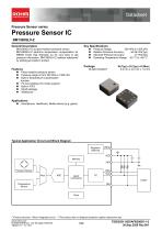
Datasheet Pressure Sensor series Pressure Sensor IC BM1390GLV-Z General Description BM1390GLV-Z is piezo-resistive pressure sensor. BM1390GLV-Z performs temperature compensation for MEMS inside chip internally, so it’s very easy to get pressure information. BM1390GLV-Z realizes waterproof by potting gel inside to protect. Pressure Range: 300 hPa to 1300 hPa Relative Pressure Accuracy: ±0.06 hPa(Typ) Absolute Pressure Accuracy: ±1 hPa(Typ) Operating Temperature Range: -40 °C to +85 °C Piezo-resistive pressure sensor Pressure range is from 300 hPa to 1300 hPa Built-in temperature compensation function. I2C bus interface (f/s mode support) Built-in FIFO Small package Waterproof Smartphone, Healthcare, Mobile device (e.g. game). Typical Application Circuit and Block Diagram Regulator (internal) Memory VSS Pressure Sensor Mux signal processing Temperature Sensor 〇Product structure : Silicon integrated circuit . www.rohm.com © 2020 ROHM Co., Ltd. All rights reserved. TSZ22111 • 14 • 001 〇This product has no designed protection against radioactive rays.
Open the catalog to page 1
. www.rohm.com © 2020 ROHM Co., Ltd. All rights reserved. TSZ22111 • 15 • 001
Open the catalog to page 2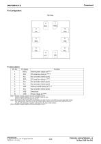
Internal power supply pin(Note 1) I2C serial bus clock pin (Note 2) I2C serial bus data pin (Note 2) Interrupt notice output pin(Note 2) (Note 1) Dispose a bypass capacitor as close as possible to the IC. Dispose a bypass capacitor of 0.1 µF between VREG and VSS. Do not use this pin for external power source. (Note 2) When there is other device which is connected to the SDA, the SCL or the DRI pins and its signal falls sharply, that might generate undershoot and the pin voltage might go below ground. When such undershoot occurs, a measure like disposing a capacitor near the pins of the device...
Open the catalog to page 3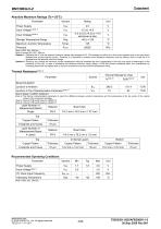
BM1390GLV-Z Absolute Maximum Ratings (Ta = 25°C) Parameter Power Supply Storage Temperature Range Maximum Junction Temperature Pressure (Note 1) DRI, SCL, SDA pin (Note 2) except DRI, SCL, SDA pin Caution 1: Operating the IC over the absolute maximum ratings may damage the IC. The damage can either be a short circuit between pins or an open circuit between pins and the internal circuitry. Therefore, it is important to consider circuit protection measures, such as adding a fuse, in case the IC is operated over the absolute maximum ratings. Caution 2: Should by any chance the maximum junction temperature...
Open the catalog to page 4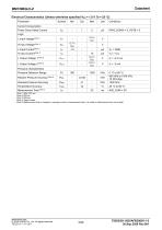
BM1390GLV-Z Electrical Characteristics (Unless otherwise specified VDD = 1.8 V Ta = 25 °C) Parameter Current Consumption Power Down Mode Current Logic Absolute Pressure Accuracy Temperature Accuracy Pressure characteristics Pressure Detection Range Relative Pressure (Note 1) SDA, SCL pin (Note 2) DRI pin (Note 3) SDA pin (Note 4) Target values (Note 5) Measurement time is changed by average number of measurement data. It is written in Measurement time more detail. . www.rohm.com © 2020 ROHM Co., Ltd. All rights reserved. TSZ22111 • 15 • 001
Open the catalog to page 5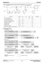
BM1390GLV-Z I2C Bus Timing Characteristics (Unless otherwise specified VDD = 1.8 V, Ta = 25 °C) VIH tBUF tHD;STA Setup Time for Repeated START Hold Time for START Data Setup Time Data Hold Time Setup Time for STOP Bus Free Time between STOP and START 1. Write Format (1) Indicate register address S Slave Address Register Address Register Address (2) Write data after indicating register address S Slave Address Data specified at register address field Data specified at register address field + N 2. Read Format (1) Read data after indicating register address S Slave Address Register Address Slave...
Open the catalog to page 6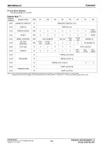
Register Map(Note 1) Register Address Register Name FIFO data (Note 1) Do not write any commands to other addresses except above. Do not write ‘1’ to the fields in which value is ‘0’ in above table. Address from 0x14 to 0x1E registers can be accessed only when PWR_DOWN = 1 and RSTB = 1. (In other case Write: Ignored, Read: 0xXX) . www.rohm.com © 2020 ROHM Co., Ltd. All rights reserved. TSZ22111 • 15 • 001
Open the catalog to page 7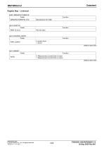
BM1390GLV-Z Register Map – continued (0x0F) MANUFACTURER ID Fields MANUFACTURER ID [7:0] (0x10) PART ID Fields PART ID [7:0] Function 0: power down 1: active default value 0x00 (0x13) RESET Fields RSTB Function 0: Measurement control block is reset 1: Measurement control block is active default value 0x00 . www.rohm.com © 2020 ROHM Co., Ltd. All rights reserved. TSZ22111 • 15 • 001
Open the catalog to page 8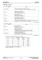
BM1390GLV-Z Register Map – continued (0x14) MODE_CONTROL Fields Seting of the averaging number of measurement data 011: 8 times, 100: 16 times, 101: 32 times, 110: 64 times, other: Prohibited DRI pin Enable for Data Ready Details are written in Interrupt. 0: DRI pin Disable, 1: DRI pin Enable DRI pin Enable for FULL Details are written in Interrupt. 0: DRI pin Disable, 1: DRI pin Enable DRI pin Enable for Water Mark Details are written in Interrupt. 0: DRI pin Disable, 1: DRI pin Enable Measurement mode setting (Pressure and Temperature are measured at one rate) 00: Standby, 01: One shot, 10:...
Open the catalog to page 9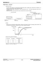
BM1390GLV-Z Register Map – continued Measurement time One shot mode performs one measurement. Measurement data is updated when measurement completed, so it should be read more than tM after measurement start. Continuous mode repeats measurement in every measurement cycle tI. The latest measurement data which is completed is read. Measurement time tM and measurement cycle tI is determined by number of average. Measurement cycle tI Pressure data of first time measurement is read. Measurement time tM Measurement First Measurement Second measurement IIR filter RMS noise can be reduced by setting...
Open the catalog to page 10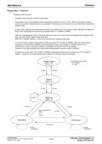
BM1390GLV-Z Register Map – continued Operation mode transition Operation mode transition is like the chart below. Power down mode is the smallest current consumption mode due to circuit is OFF. Set this mode when reducing current consumption. Measurement is not available in this mode, so the measurement is performed after switching to standby mode. In reset mode, regulator for internal blocks is active and measurement control block is reset. Register is initialized in Reset mode. Measurement command is acceptable when “1” is written in “RSTB” There are 2 measurement modes. One shot mode and Continuous...
Open the catalog to page 11All ROHM Semiconductor catalogs and technical brochures
 PSR series
17 Pages
 Microcontrollers
32 Pages
 Speech Synthesis LSI Series
20 Pages
 Next-Generation Op Amp series
12 Pages
 LED
LED18 Pages
 Diodes
30 Pages
 Intelligent Power Modules
3 Pages
 Full SiC Power Modules
3 Pages
 SiC Schottky Barrier Diodes
4 Pages
 Microcontroller
13 Pages
 Audio & Video
11 Pages
 Sensors & MEMS
4 Pages
 LED Drivers
4 Pages
 Power Management
36 Pages
 Data Converter
2 Pages
 Clocks & Timers
2 Pages
 Memory
6 Pages
 Motor Drivers
44 Pages
 Power Device Catalog
36 Pages
 CSL1501RW
9 Pages
 UT6JC5 -60V Pch+Pch Power MOSFET
14 Pages
 SH8JB5 -40V Pch+Pch Power MOSFET
14 Pages
 CSL1104WBx Series (x=A/B/C/D)
11 Pages
 BD9F500QUZ
58 Pages
 RGW00TS65CHR
15 Pages
 RGW80TS65CHR
15 Pages
 RGW60TS65CHR
15 Pages
 QH8KC5
14 Pages
 QH8KC6
14 Pages
 QH8KB5
14 Pages
 QH8KB6
14 Pages
 SH8KC6
14 Pages
 SH8KC7
14 Pages
 SH8KB6
14 Pages
 SH8KB7
14 Pages
 QH8MB5
22 Pages
 SH8MB5
22 Pages
 RPMD-0100
5 Pages
 Short Form Catalog
308 Pages
 EMARMOUR Technology
4 Pages
 Industrial Motor Solutions
40 Pages
 General-purpse ICs
40 Pages
 IPD
IPD4 Pages
 Quick Buck Booster®
6 Pages
 SOT-23 Package Products
4 Pages
 DC/DC Converter Selection Guide
40 Pages
 Linear Regulator Selection Guide
32 Pages
 Sensing Networks Catalog
11 Pages
 Power Solutions Catalog
9 Pages
 Power Management
11 Pages
 Motor Drivers
36 Pages
 Automotive Product Catalog
124 Pages
 EV solutions
8 Pages


Archived catalogs

- Single-pole switch
- DC-DC converter
- Technology switch
- Diode
- Transistor module
- Industrial DC/DC converter module
- SMD DC-DC converter
- ERLO board-mount resistor
- ERLO power resistor
- Switching transistor
- High-speed diode
- Motor driver
- MOSFET transistor
- Power converter
- SMT diode
- Current rectifier
- Bipolar transistor
- ERLO thin-film resistor
- Switching DC-DC converter
- Step-down DC-DC converter