- Catalogs
- ROHM Semiconductor
- 600V IGBT Intelligent Power Module (IPM) BM64378S-VA
600V IGBT Intelligent Power Module (IPM) BM64378S-VA
1 /23Pages

600V IGBT Intelligent Power Module (IPM) BM64378S-VA
1 /23Pages
Catalog excerpts

Datasheet Inverter for motor control 600V IGBT Intelligent Power Module (IPM) BM64378S-VA General Description BM64378S-VA is an Intelligent Power Module composed of gate drivers, bootstrap diodes, IGBTs, fly wheel diodes. Key Specifications IGBT Collector-Emitter Voltage VCESAT: 1.5V(Typ) FWD Forward Voltage VF: 1.7V(Typ) FWD Reverse Recovery Time trr: 100ns(Typ) Module Case Temperature TC: -25 to +115°C Junction Temperature Tjmax: 150°C Features 3phase DC/AC Inverter 600V/35A Low Side IGBT Open Emitter Built -in Bootstrap Diode High Side IGBT Gate Driver(HVIC): SOI (Silicon On Insulator) Process, Drive Circuit, High Voltage Level Shifting, Current Limit for Bootstrap Diode, Control Supply Under-Voltage Locked Out (UVLO) Low Side IGBT Gate Driver(LVIC): Drive Circuit, Short Circuit Current Protection (SCP), Control Supply Under Voltage Locked Out (UVLO), Thermal Shutdown (TSD), Temperature Output by Analog Signal (VOT) Fault Signal(LVIC) Corresponding to SCP (Low Side IGBT), TSD, UVLO Fault Input Interface 3.3V, 5V Line UL Recognized: UL1557 File E468261 W(Typ) x D(Typ) x H(Typ) 38.0mm x 24.0mm x 3.5mm Application AC100 to 240Vrms(DC Voltage: Less Than 400V) Class Motor Control Compressor Motor Control for Air Conditioner, Washing Machine, Refrigerator Typical Application Circuit 2 Figure 1. Example of Application Circuit ○Product structure: Semiconductor IC ○This product is not designed for protection against radioactive rays . www.rohm.com TSQ50501-BM64378S-2 © 2020 ROHM Co., Ltd. All rights reserved. 1/20
Open the catalog to page 1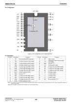
LVCC LINW HINW HINV HINU VBW VBV Figure 2. Pin Configuration and Tc Detecting Point Pin Description Pin No. Pin Name U phase floating control supply V phase floating control supply Alarm output Detecting of short circuit current trip voltage Ground (Note 1) W phase floating control supply Temperature output U phase high side IGBT control W phase low side IGBT emitter V phase high side IGBT control V phase low side IGBT emitter W phase high side IGBT control U phase low side IGBT emitter Control supply for HVIC U phase low side IGBT control Inverter supply V phase low side IGBT control W phase...
Open the catalog to page 2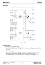
Block Diagram High Side Gate Driver (HVIC) HINU HINV HINW LINU LINV LINW NU Low Side Gate Driver (LVIC) NV Figure 3. Block Diagram Description of Block 1) High Side IGBT Drive (HVIC, Bootstrap Diode) High voltage level shifting circuit drives high side IGBT. Built-in bootstrap diode and current limit function for bootstrap diode enable HVIC to drive high side IGBT without external component (bootstrap diode, resistor). There is under-voltage-locked-out (UVLO) function for floating control power supply. 2) Low Side IGBT Drive (LVIC) LVIC drives low side IGBT. There is short circuit current protection...
Open the catalog to page 3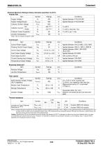
Absolute Maximum Ratings (Unless otherwise specified, Tj=25°C) Inverter Part Item Symbol Ratings Unit Supply Voltage Supply Voltage(Surge) Collector-Emitter Voltage Collector Current Applied between P-NU,NV,NW Applied between P-NU,NV,NW TC=25°C, less than 1ms TC=25°C, per 1 chip Collector Power Dissipation Junction Temperature (Note 1) Do not, however exceed PC, ASO. Control part Symbol Control Power Supply Applied between HVCC-GND, LVCC-GND Floating Control Power Supply Control Input Voltage Fault Output Supply Voltage Applied between VBU-U, VBV-V, VBW-W Applied between HINX, LINX-GND (X=U,V,W)...
Open the catalog to page 4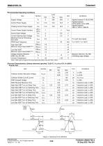
Recommended Operating Conditions Item Conditions Applied between P-NU,NV,NW Applied between HVCC-GND, LVCC-GND Applied between VBU-U, VBV-V, VBW-W Supply Voltage Control Power Supply Floating Control Power Supply Control Power Supply Variation Control Input Voltage Current Sensing Input Voltage Blanking Time for Preventing Arm-short PWM Input Frequency High Side IGBT Minimum Input Pulse Width(Note1) Low Side IGBT Minimum Input Pulse Width(Note1) For each input signal Voltage Variation Between GND- NU, NV, NW Junction Temperature Between GND-NU, NV, NW (Including surge voltage) (Note 1) IPM might...
Open the catalog to page 5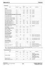
BM64378S-VA Control part Item Whole VCC Circuit Current 1 Control Input(HINU,HINV,HINW,LINU,LINV,LINW) H Level Input Current L Level Input Current H Level Input Threshold Voltage L Level Input Threshold Voltage Input Hysteresis Voltage HINU-GND Resistance HINV-GND HINW-GND Resistance (Note 1) Short Circuit Current Protection CIN Input Bias Current Trip Voltage Under Voltage Locked Out Monitor LVIC temperature Monitor LVIC temperature During VCC UVLO Operation Thermal Shutdown Trip Temperature Hysteresis Temperature Temperature Output VOT Voltage Fault Output(FO) Output low Voltage Leak Current...
Open the catalog to page 6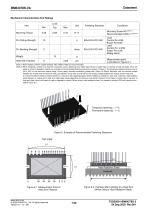
Mechanical Characteristics And Ratings Item Following Standard Mounting Screw M3 (Note 1) Recommended 0.69N・m (Note 2) Heat Sink Flatness Mounting Torque Load Control Pin:4.9N Power Pin:9.8N Load Control Pin: 2.45N Power Pin:4.9N 90deg. Bend Measurement point is provided in Figure 6-1. (Note 1) Plain washers of 8mm outside diameter (ISO 7089 to 7094) are recommended. (Note 2) When installing a module to a heat sink, excessive uneven fastening force might apply stress to inside chips or ceramic of heat sink plate, which will break or crack or degrade a module. An example of recommended fastening...
Open the catalog to page 7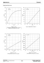
Typical Performance Curve 200 Figure 8. Magnification of Figure 7 Figure 7. IF vs VF Characteristic of Bootstrap Diode IF-VF Curve Between HVCC-VBX pin (X=U,V,W) Figure 10. VOT vs LVIC Tj (Characteristic of VOT pin VOT-Tj Curve) Figure 9. VFO vs IFO (Characteristic of FO pin VFO-IFO Curve) www.rohm.com © 2020 ROHM Co., Ltd. All rights reserved. TSZ22111・15・001
Open the catalog to page 8
Timing Chart 1) Short Circuit Current Protection (protection with the external shunt resistor and RC filter) a1. Normal operation: IGBT ON and outputs current IC. a2. Short circuit current detection (SCP trigger) It is recommended to set RC time constant of 1.0µs so that IGBT shuts down within 2.0µs when SCP is triggered. a3. All low side IGBT’s gates are shut down (soft turn off). a4. All low side IGBTs turn off. a5. FO outputs for tFO=45µs (Min). a6. LIN=L a7. LIN=H, but all IGBTs keep OFF during SCP=H. a8. FO finishes output , but IGBTs don’t turn on until inputting the next ON signal(LIN=L→H)...
Open the catalog to page 9All ROHM Semiconductor catalogs and technical brochures
 PSR series
17 Pages
 Microcontrollers
32 Pages
 Speech Synthesis LSI Series
20 Pages
 Next-Generation Op Amp series
12 Pages
 LED
LED18 Pages
 Diodes
30 Pages
 Intelligent Power Modules
3 Pages
 Full SiC Power Modules
3 Pages
 SiC Schottky Barrier Diodes
4 Pages
 Microcontroller
13 Pages
 Audio & Video
11 Pages
 Sensors & MEMS
4 Pages
 LED Drivers
4 Pages
 Power Management
36 Pages
 Data Converter
2 Pages
 Clocks & Timers
2 Pages
 Memory
6 Pages
 Motor Drivers
44 Pages
 Power Device Catalog
36 Pages
 CSL1501RW
9 Pages
 UT6JC5 -60V Pch+Pch Power MOSFET
14 Pages
 SH8JB5 -40V Pch+Pch Power MOSFET
14 Pages
 CSL1104WBx Series (x=A/B/C/D)
11 Pages
 BD9F500QUZ
58 Pages
 RGW00TS65CHR
15 Pages
 RGW80TS65CHR
15 Pages
 RGW60TS65CHR
15 Pages
 QH8KC5
14 Pages
 QH8KC6
14 Pages
 QH8KB5
14 Pages
 QH8KB6
14 Pages
 SH8KC6
14 Pages
 SH8KC7
14 Pages
 SH8KB6
14 Pages
 SH8KB7
14 Pages
 QH8MB5
22 Pages
 SH8MB5
22 Pages
 BM1390GLV-Z
31 Pages
 RPMD-0100
5 Pages
 Short Form Catalog
308 Pages
 EMARMOUR Technology
4 Pages
 Industrial Motor Solutions
40 Pages
 General-purpse ICs
40 Pages
 IPD
IPD4 Pages
 Quick Buck Booster®
6 Pages
 SOT-23 Package Products
4 Pages
 DC/DC Converter Selection Guide
40 Pages
 Linear Regulator Selection Guide
32 Pages
 Sensing Networks Catalog
11 Pages
 Power Solutions Catalog
9 Pages
 Power Management
11 Pages
 Motor Drivers
36 Pages
 Automotive Product Catalog
124 Pages
 EV solutions
8 Pages


Archived catalogs

- Single-pole switch
- DC-DC converter
- Technology switch
- Transistor module
- Industrial DC/DC converter module
- SMD DC-DC converter
- ERLO board-mount resistor
- ERLO power resistor
- Switching transistor
- High-speed diode
- Motor driver
- MOSFET transistor
- Power converter
- SMT diode
- Current rectifier
- Bipolar transistor
- ERLO thin-film resistor
- Switching DC-DC converter
- Step-down DC-DC converter