
- Catalogs
- Rohde Schwarz
- SMU200A Vector Signal Generator


SMU200A Vector Signal Generator

SMU200A Vector Signal Generator
The R&S®SMU200A Vector Signal Generator is designed for research, development, and production in modern communication systems. It features up to two independent signal generators in a compact unit, offering exceptional RF and baseband characteristics with frequency options from 100 kHz to 6 GHz.
The device includes two signal generators, a color display for intuitive operation, and outstanding signal quality with low phase noise and high output power. It supports various digital standards and offers flexibility with options like MIMO and fading simulation, making it ideal for production due to its fast frequency and level setting times.
RF path A supports frequencies up to 6 GHz, while RF path B supports up to 3 GHz. Enhancement options include improved phase noise performance and FM/φM modulation capabilities, with high-power output options available for both RF paths.
The generator supports multiple modulation types, including amplitude, frequency, phase, vector, and digital modulation. Simultaneous modulation is possible within the same RF path, allowing combinations like amplitude and frequency modulation.
The document outlines compatibility settings for various modulation types, with specific modes requiring the switching off of others.
The frequency range varies from 100 kHz to 6 GHz, with a frequency setting resolution of 0.01 Hz and a synthesis resolution of 5 µHz. Frequency sweep modes include digital sweep in discrete steps with various trigger options.
Details on reference frequency stability, aging rates, and temperature effects are provided, with a warm-up time to nominal thermostat temperature of ≤10 minutes.
The level setting range is from -145 dBm to +20 dBm, extendable to +30 dBm with certain options. Level uncertainty and setting time are specified, along with ALC state and attenuator modes.
Harmonics and nonharmonics are detailed with specific dBc levels across different frequency ranges, along with wideband noise and SSB phase noise specifications.
Various modulation types are described, including amplitude, pulse, frequency, and phase modulation, with detailed specifications for each. I/Q modulation is also covered, with settings for I/Q impairments and external wideband I/Q input.
Graphs show measured maximum available output levels, level uncertainty, and SSB phase noise across different frequencies, providing visual insights into performance characteristics.
The list mode allows storing frequency and level values for quick setting changes. The internal modulation generator and its specifications are detailed, including frequency range and output voltage settings.
- R&S®SMU-B13: Drives RF paths A and B with a data rate of 100 MHz and a resolution of 16 bits.
- R&S®SMU-B16: Offers differential I/Q output with specific output impedances.
- R&S®SMU-B18: Provides digital I/Q outputs for lossless connection to other instruments.
- Output impedance is 50 Ω with an output voltage EMF of 1 V (Vp).
- Frequency response and I/Q balance are optimized for RF output.
- Supports various modulation types with specific parameters.
- Baseband filters include cosine, root cosine, and Gaussian with adjustable parameters.
- R&S®SMU-B17 option allows for external analog or digital signals to be fed into the baseband section.
- Digital I/Q inputs conform to R&S®TVR290 standards.
- Carrier leakage is referenced to full-scale input at <−55 dBc.
- Wideband noise and spectral purity are maintained with phase noise at −150 dBc for a 10 MHz sinewave at 20 kHz offset.
- Multicarrier waveform capabilities with a maximum of 32 carriers.
- Triggering options include internal and external modes.
The device supports both internal and external clock modes with specific settings for trigger synchronization.
The generator supports a wide range of digital standards, with modulation errors specified for various types.
Numerous software options for different digital standards are listed, requiring specific hardware configurations.
Options for fading simulation are included, with capabilities for dynamic fading and enhanced resolution.
Key performance metrics such as ACPR, phase error, and EVM are detailed for different standards and configurations.
The R&S®SMU200A Vector Signal Generator is a versatile tool for generating and testing a wide range of digital communication standards, with extensive options for modulation, triggering, and fading simulation.
Catalog excerpts

Version 07.00 ¸SMU200A Vector Signal Generator December 2007 Data sheet Titel+Rück_SMU200A_specs_en.indd1 1 28.12.2007 11:21:43
Open the catalog to page 1
Introduction ® The R&S SMU200A vector signal generator has been designed to meet all requirements encountered in the research and ® development of modern communications systems as well as in their production. The R&S SMU200A not only combines up to two independent signal generators in one cabinet of only four height units, but also offers unrivaled RF and baseband characteristics. ® Due to its modular design, the R&S SMU200A can be optimally adapted to the requirements of different applications. The first RF path can be equipped with one of the four available frequency options. The upper frequency...
Open the catalog to page 4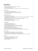
Key features Two signal generators in one • • • • Frequency options from 100 kHz to 2.2/3/4/6 GHz for the first RF path Optional second RF path up to 2.2 GHz or 3 GHz Up to two complete baseband paths Lossless combination of baseband signals in the digital domain (e.g. for testing multistandard base stations) Intuitive operation • • • • Color display with 800 × 600 pixels (SVGA format) Intuitive user interface with graphical display of signal flow (block diagram) Graphical display of baseband signals through built-in transient recorder Context-sensitive help system Outstanding signal quality...
Open the catalog to page 5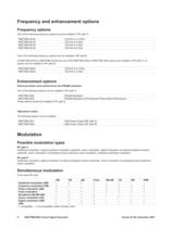
Frequency and enhancement options Frequency options One of the following frequency options must be installed in RF path A: One of the following frequency options can be installed in RF path B: (If R&SBSMU-B104 or R&SBSMU-B106 and one of the R&SBSMU-B20 or R&SBSMU-B22 options are installed in RF path A, no options can be installed in RF path B.) Enhancement options Enhanced phase noise performance and FM/cpM modulator One of the following options can be installed in RF path A: These options cannot be installed in RF path B. High-power output The following options can be installed Possible modulation...
Open the catalog to page 6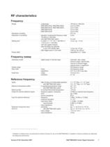
Frequency sweep Reference frequency Installation of software that is not authorized by Rohde & Schwarz for use on the R&S®SMU200A or installation of antivirus software can deteriorate the setting time performance. R&S®SMU200A Vector Signal Generator
Open the catalog to page 7
2 PEP = peak envelope power. 3 Installation of software that is not authorized by Rohde & Schwarz for use on the R&S®SMU200A or installation of antivirus software can deteriorate the setting time performance. 8 R&S®SMU200A Vector Signal Generator Version 07.00, December 2007
Open the catalog to page 8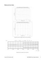
Measured level data Max. available output power with frequency option B106, Attenuator Mode Normal (lower trace) and High Power (upper trace) Max. available output power with frequency option B103, Attenuator Mode Normal (lower trace) and High Power (upper trace) Measured maximum available output level versus frequency Measured level uncertainty versus frequency Version 07.00, December 2007 R&S®SMU200A Vector Signal Generator 9
Open the catalog to page 9
La/el Repeatability (2GHz, OdBm, ALC=ON) DACIF-Board Temperature Level repeatability over 6 days with random settings between measurements (DA CIF board temperature: internal temperature test point, variations caused by changes of ambient temperature) Level sweep 10 R&S®SMU200A Vector Signal Generator
Open the catalog to page 10
Spectral purity Harmonics Nonharmonics ® Nonharmonics with R&S SMU-B22 option Power supply and mechanically related nonharmonics Subharmonics Wideband noise SSB phase noise Version 07.00, December 2007 standard, unmodulated level <8 dBm level <13 dBm ® ® with R&S SMU-B31 or R&S SMU-B36 option, level <12 dBm level >–50 dBm, CW, vector modulation (full-scale DC input), >10 kHz offset from carrier and outside the modulation spectrum 0.3 MHz ≤ f ≤ 200 MHz 200 MHz < f ≤ 1500 MHz 1500 MHz < f ≤ 3000 MHz f > 3000 MHz >850 kHz offset from carrier and outside the modulation spectrum 0.3 MHz ≤ f ≤ 200...
Open the catalog to page 11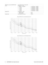
® SSB phase noise with R&S SMU-B22 option Residual FM Residual AM carrier offset 20 kHz, measurement bandwidth 1 Hz, CW 20 MHz ≤ f ≤ 200 MHz f = 1 GHz f = 2 GHz f = 3 GHz f = 4 GHz f = 6 GHz rms value at f = 1 GHz 300 Hz to 3 kHz 20 Hz to 23 kHz rms value 20 Hz to 23 kHz <–135 dBc (typ. –138 dBc) <–136 dBc (typ. –139 dBc) <–130 dBc (typ. –133 dBc) <–126 dBc (typ. –129 dBc) <–124 dBc (typ. –127 dBc) <–120 dBc (typ. –123 dBc) <1 Hz <4 Hz <0.02 % Measured SSB phase noise, I/Q modulated (typical values) -40 -50 SSB phase noise / dBc (1Hz meas. bandwidth) -60 -70 -80 5.7 GHz -90 2.1 GHz -100 850 MHz...
Open the catalog to page 12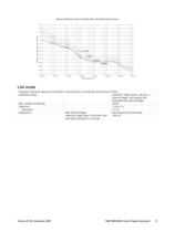
Measured SSB phase noise with Option B22, unmodulated (typical values) -40 -50 SSB phase noise / dBc (1Hz meas. bandwidth) -60 -70 -80 -90 -100 5.7 GHz -110 -120 2.1 GHz -130 100 MHz -140 850 MHz -150 -160 -170 1,0E+00 1,0E+01 1,0E+02 1,0E+03 1,0E+04 1,0E+05 1,0E+06 1,0E+07 Offset frequency / Hz List mode Frequency and level values can be stored in a list and set in an extremely short amount of time. Operating modes automatic, single sweep, manual, or external trigger, fast hopping with immediate and external trigger Max. number of channels 10000 Dwell time 1 ms to 1 s Resolution 0.1 ms Setting...
Open the catalog to page 13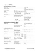
Analog modulation Internal modulation generator Input for external modulation signals Amplitude modulation Wideband amplitude modulation 14 R&S®SMU200A Vector Signal Generator
Open the catalog to page 14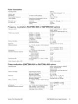
Pulse modulation Frequency modulation (R&S®SMU-B20 or R&S®SMU-B22 option) Phase modulation (R&S®SMU-B20 or R&S®SMU-B22 option) R&S®SMU200A Vector Signal Generator 15
Open the catalog to page 15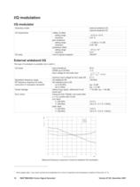
This type of modulation is possible only in path A. Frequency offsetfrom carrier/MHz - Measured frequency response of external wideband l/Q modulation 4 Value applies after 1 hour warm-up time and recalibration for 4 hours of operation and temperature variations of less than +5 °C. 16 R&S®SMU200A Vector Signal Generator Version 07.00, December 2007
Open the catalog to page 16All Rohde Schwarz catalogs and technical brochures
 R&S®ZNL vector network analyzer
18 Pages
 R&S®MXO 4 Oscilloscope
40 Pages
 R&S®RTE1000 oscilloscope
40 Pages
 R&S®FPL1000
20 Pages
 R&S®ZNA vector network analyzers
52 Pages
 R&S®HF907
2 Pages
 R&S®RO129 Antenna Rotator
6 Pages
 R&S®PR100 Portable Receiver
30 Pages
 R&S®ETC Compact TV Analyzer
12 Pages
 R&S®RSC Step Attenuator
10 Pages


Archived catalogs
 R&S®RTA4000 Oscilloscope
22 Pages
 R&S®NRP Power Meter Family
40 Pages
 R&S®EVSF1000
12 Pages
 R&S®UMS175
10 Pages
 R&S®AVHE100
24 Pages
 HM8030
2 Pages
 R&S®HMC8015 Power Analyzer
10 Pages
 R&S®HM8118 LCR-Bridge
2 Pages
 Digital Multimeter HMC8012
3 Pages
 R&S®TSMX-PPS2 GPS Module
4 Pages
 Mobile network testing solutions
20 Pages
 Value Instruments Catalog
69 Pages
 Test & Measurement Catalog 2016
266 Pages
 Test & Measurement Catalog 2013/2014
214 Pages
 R&S®BBA150 Broadband Amplifier
16 Pages
 R&S®UPZ Audio Switcher
6 Pages
 R&S®SMZ Frequency Multiplier
8 Pages
 R&S®CMW-CU Control Unit
6 Pages
 R&S®FSQ Signal Analyzer
14 Pages
 R&S®FSU Spectrum Analyzer
16 Pages
 R&S®RTE-B1 Mixed Signal, 400 MHz
26 Pages
 R&S®RTO Digital Oscilloscopes
32 Pages
 R&S®ZVB Vector Network Analyzers
20 Pages
 R&S®IQR I/Q Data Recorde
16 Pages
 R&S®CMA180 Radio Test Set
16 Pages
 R&S®UPV Audio Analyzer
24 Pages
 R&S®CBT/CBT32 Bluetooth® Tester
20 Pages
 R&S®RTE Digital Oscilloscope
26 Pages
 R&S®CMW500 Platform overview
20 Pages
 R&S®EM010 VXI HF Receiver
10 Pages
 EMC Precompliance Solutions
79 Pages
 UMS120 Monitoring Syste
8 Pages
 R&S®FPC Spectrum analyzer
16 Pages
 Broadcasting Catalog
144 Pages
 Secure communication Catalog
274 Pages
 T & M Product Catalog
146 Pages
 R&S®RF Step Attenuators
2 Pages
 Q8384 Optical Spectrum Analyzer
10 Pages
 R&S®NRP Power Meter
22 Pages
 Audio Analyzers ¸UP 300/¸UP 350
16 Pages
 R&S®ZVL Vector Network Analyzers
14 Pages
 R&S®EVS300 ILS/VOR Analyzer
12 Pages
 SMU200A Flyer
2 Pages
 WiMAX Communication Tester
16 Pages
 Network Operators Catalog
18 Pages


- Rohde & Schwarz DC power supply
- AC/DC power supply
- Test cabinet
- Monitoring analyzer
- Temperature test chamber
- Automatic analyser
- Single-output power supply
- Benchtop analyser
- Power supply for industrial applications
- Quality control test cell
- Portable tester
- Environmental test chamber
- Portable analyzer
- Signal amplifying integrated circuit
- Rohde & Schwarz power supply with overload protection
- Rohde & Schwarz tabletop power supply
- Compact power supply
- Automatic tester