- Catalogs
- Rohde Schwarz
- R&S®CMA180 Radio Test Set
R&S®CMA180 Radio Test Set
1 /16Pages

R&S®CMA180 Radio Test Set
1 /16Pages
Catalog excerpts
Test & Measurement R&S®CMA180 Radio Test Set The new reference in radio testing
Open the catalog to page 1
R&S®CMA180 Radio Test Set At a glance The R&S®CMA180 is a radiocommunications tester for radio systems that operate in the 100 kHz to 3 GHz range. Its technology is based fully on digital signal processing and advanced computing. Intuitive operation and efficient measurement capabilities make the R&S®CMA180 an indispensable tool for performing radio measurements. The R&S®CMA180 demodulates and modulates all common analog RF signals, making it ideal for testing transmitters and receivers. For receiver tests, audio signals from the internal generators or from external sources can be modulated onto...
Open the catalog to page 2
R&S®CMA180 Radio Test Set Benefits and key features All-purpose ❙❙ Diverse, future-ready configuration options ▷▷ page 4 Extensive measurement functionality ❙❙ Analog modulation and demodulation ❙❙ Audio generators ❙❙ Audio quality tests ❙❙ Built-in interferer ❙❙ Waveforms (ARB) ❙❙ FFT spectrum analyzer ❙❙ Built-in sweeping spectrum analyzer with time domain analysis (zero span) ▷▷ page 5 Convenient operation ❙❙ Advanced touchscreen plus rotary knob ❙❙ Predefined test scenarios for minimal configuration effort, or expert mode for maximum freedom ❙❙ Different possibilities for displaying parameters...
Open the catalog to page 3
Diverse, future-ready configuration options With its frequency range from 100 kHz to 3 GHz, the R&S®CMA180 is ideal for testing all common analog radio systems. Input levels up to 150 W are no problem for the R&S®CMA180. The flexible internal switching capabilities for the audio and RF paths make the R&S®CMA180 suitable for a wide range of test requirements. Users can configure the internal generators, external audio sources, filters and measurements according to the given application. In the predefined test scenarios for receiver, transmitter and duplex tests, the RF and audio paths are preconfigured....
Open the catalog to page 4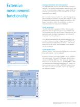
Maximum Freq. Deviation Main Interferer Frequency modulation with an internal audio Analyzer | EPS j Power | FFT Spectn StdDev Unit Analog modulation and demodulation methods. For receiver measurements, external signals that are fed in via the analog or digital audio inputs, as well as internally generated signals and audio files, can be modu- lated onto an RF carrier. For transmitter measurements, the transmitter signals are demodulated and analyzed. The spectrum analyzer is used to display demodulated audio signals. Depending on the type of modulation, either the modulation deviation or modulation...
Open the catalog to page 5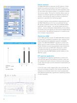
Built-in interferer The R&S®CMA180 can generate two RF signals. If these signals are positioned outside of the DUT's receive win- dow in such a way that at least one intermodulation prod- uct lies within the receive window, it is possible to assess the receiver quality. The built-in interferer allows users to measure co-channel rejection and adjacent channel sup- pression, eliminating the need to employ an additional generator to generate the interfering signal. It is easy to perform intermodulation measurements with the R&S®CMA180 since the user can generate the two RF signals at different levels...
Open the catalog to page 6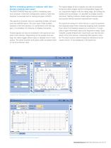
Built-in sweeping spectrum analyzer with time domain analysis (zero span) The R&S®CMA180 features a built-in sweeping spectrum analyzer. Extensive configuration options make this a nalyzer a universal tool for testing all types of DUTs. The spectrum analyzer has two operating modes: full span and user-defined spans. The zero span mode enables a nalysis in the time domain. In combination with the triggers, it is possible, for instance, to display transients. Pulsed signals can also be analyzed in the spectrum analyzer's time domain. Depending on the sweep time setting, the video trigger allows...
Open the catalog to page 7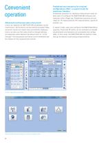
Advanced touchscreen plus rotary knob Users can operate the R&S®CMA180 completely via the touchscreen. All functions can be quickly accessed. Mea- surement results are clearly and conveniently displayed. Users can also use the rotary knob to change settings, an especially useful feature that allows them to "scroll through" the frequencies and levels and immediately see the impact on the measurement results. Predefined test scenarios for minimal configuration effort, or expert mode for maximum freedom Predefined scenarios for standard measurement tasks en- able users to configure the R&S®CMA180...
Open the catalog to page 8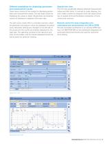
Different possibilities for displaying parameters Users have a choice of two modes for displaying param- eters and measurement results. The tab mode is best for displaying the values in detail. All generator and analyzer values are displayed in separate full-screen tabs. The split screen mode offers a complete overview, where the generator and analyzer values are displayed simultane- ously. Generator settings are changed on the left side of the screen and the results are instantly displayed on the right side. The operating controls for the spectrum ana- lyzer can be hidden, and the results displayed...
Open the catalog to page 9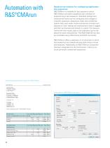
Automation with Ready-to-use solution for configuring application test sequences R&S®CMArun is available for test sequence control. R&S®CMArun provides a graphical user interface for programming a test sequence. Individual settings and measurement tasks can be configured and arranged in a specific sequence. Sequences, loops and conditional queries help users easily create and execute complex test sequences. Each setting and measurement value is logged and then summarized and stored in a report. For measure- ments with limit values, pass or fail indicators can be dis- played for each measurement....
Open the catalog to page 10
receiver tests For RF transmitter tests, all relevant parameters are mea- sured, including transmit power, transmit frequency, fre- quency error and modulation parameters. The transmit power can be as high as 150 W. A spectrum analyzer is available for examining the signals in the frequency do- main. Harmonics and the adjacent channel power can also To investigate the receiver's sensitivity, RF signals are gen- erated at very low powers. The signal power can be re- duced to as low as -140 dBm. To analyze the audio signal, the audio signal demodulated by the DUT can be played Many different connectivity...
Open the catalog to page 11All Rohde Schwarz catalogs and technical brochures
 R&S®ZNL vector network analyzer
18 Pages
 R&S®MXO 4 Oscilloscope
40 Pages
 R&S®RTE1000 oscilloscope
40 Pages
 R&S®FPL1000
20 Pages
 R&S®ZNA vector network analyzers
52 Pages
 R&S®HF907
2 Pages
 R&S®RO129 Antenna Rotator
6 Pages
 R&S®PR100 Portable Receiver
30 Pages
 R&S®ETC Compact TV Analyzer
12 Pages
 R&S®RSC Step Attenuator
10 Pages


Archived catalogs
 R&S®RTA4000 Oscilloscope
22 Pages
 R&S®NRP Power Meter Family
40 Pages
 R&S®EVSF1000
12 Pages
 R&S®UMS175
10 Pages
 R&S®AVHE100
24 Pages
 HM8030
2 Pages
 R&S®HMC8015 Power Analyzer
10 Pages
 R&S®HM8118 LCR-Bridge
2 Pages
 Digital Multimeter HMC8012
3 Pages
 R&S®TSMX-PPS2 GPS Module
4 Pages
 Mobile network testing solutions
20 Pages
 Value Instruments Catalog
69 Pages
 Test & Measurement Catalog 2016
266 Pages
 Test & Measurement Catalog 2013/2014
214 Pages
 R&S®BBA150 Broadband Amplifier
16 Pages
 R&S®UPZ Audio Switcher
6 Pages
 R&S®SMZ Frequency Multiplier
8 Pages
 R&S®CMW-CU Control Unit
6 Pages
 R&S®FSQ Signal Analyzer
14 Pages
 R&S®FSU Spectrum Analyzer
16 Pages
 R&S®RTE-B1 Mixed Signal, 400 MHz
26 Pages
 R&S®RTO Digital Oscilloscopes
32 Pages
 R&S®ZVB Vector Network Analyzers
20 Pages
 R&S®IQR I/Q Data Recorde
16 Pages
 R&S®UPV Audio Analyzer
24 Pages
 R&S®CBT/CBT32 Bluetooth® Tester
20 Pages
 R&S®RTE Digital Oscilloscope
26 Pages
 R&S®CMW500 Platform overview
20 Pages
 R&S®EM010 VXI HF Receiver
10 Pages
 EMC Precompliance Solutions
79 Pages
 UMS120 Monitoring Syste
8 Pages
 R&S®FPC Spectrum analyzer
16 Pages
 Broadcasting Catalog
144 Pages
 Secure communication Catalog
274 Pages
 T & M Product Catalog
146 Pages
 R&S®RF Step Attenuators
2 Pages
 Q8384 Optical Spectrum Analyzer
10 Pages
 R&S®NRP Power Meter
22 Pages
 Audio Analyzers ¸UP 300/¸UP 350
16 Pages
 R&S®ZVL Vector Network Analyzers
14 Pages
 SMU200A Vector Signal Generator
44 Pages
 R&S®EVS300 ILS/VOR Analyzer
12 Pages
 SMU200A Flyer
2 Pages
 WiMAX Communication Tester
16 Pages
 Network Operators Catalog
18 Pages


- Rohde & Schwarz power supply
- Rohde & Schwarz DC power supply
- AC/DC power supply
- Test cabinet
- Monitoring analyzer
- Automatic analyser
- Temperature test chamber
- Single-output power supply
- Benchtop analyser
- Power supply for industrial applications
- Quality control test cell
- Portable tester
- Portable analyzer
- Environmental test chamber
- Signal amplifying integrated circuit
- Rohde & Schwarz power supply with overload protection
- Rohde & Schwarz tabletop power supply
- Compact power supply
- Automatic tester