- Catalogs
- ROEMHELD NORTH AMERICA
- B 1.849 Compact Swing Clamps
B 1.849 Compact Swing Clamps
1 /4Pages

B 1.849 Compact Swing Clamps
1 /4Pages
Catalog excerpts

B 1.849 Compact Swing Clamps bottom flange, top flange, threaded-body type, single acting, max. operating pressure 350 bar Connecting types bottom with O-ring sealing Application Hydraulic swing clamps are used for clamping of workpieces when it is essential to keep the clamping area free of straps and clamping l components for unrestricted workpiece oading and unloading. top with O-ring sealing Function This hydraulic clamping element is a pull-type cylinder where a partSchwenkhub Swing stroke of the total stroke is used to swing the piston. r wipe FKM ard stand Swing direction The units are available with clockwise and coun terclockwise swing motion or without swing motion (0°) Clamping stroke Version Only single-acting elements are available. Important notes Operating conditions, tolerances and other data see data sheet A 0.100. It is absolutely necessary to follow the instructions for venting of the spring area on data sheet G 0.110. Double-acting elements see data sheet B 1.8491. Adjustable swing direction The swing direction of each swing clamp can also be changed, as described in the perating o instructions. Standard swing angles are 45°, 60° and 90° ±2°. Special angles on request. Other variants, as e.g. versions with metallic w iper on request. 0°-Version Use as pure pull-type cylinder with a piston which is secured against torsion and which e allows ccentric load as per clamping force diagram. ROEMHELD · 927 Horan Drive, Fenton, MO 63026 · Phone: (314) 386-8022 · Fax: (314) 386-8034 · [email protected] Actual issue see www.roemheld
Open the catalog to page 1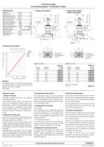
Technical data Connecting types • Important notes Counterbore for socket head cap screw M5 - DIN 912 Clamping stroke Counterbore for socket head cap screw M5 - DIN 912 Clamping stroke with O-ring sealing Technical data Piston Ø [mm] 14 Piston rod Ø [mm] 10 Effective piston area [cm2] 0,754 Oil volume per stroke [cm3] 1,2 Max. oil flow rate [cm3/s] 2,5 Min. oper. pressure [bar] 30 Max. oper. pressure [bar] 350 Max. force to pull [kN] 2,55 see diagram [kN] Effective clamping force Spring force (s.a.) [N] 40–89 Angle of rotation [°] (0,45,60,90) ± 2 Swing stroke [mm] 10 Clamping stroke [mm] 6 [mm]...
Open the catalog to page 2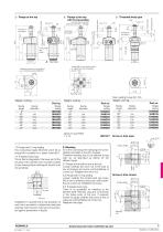
Swing stroke Clamping stroke Knife edge Clamping stroke Clamping stroke Accessories see page 4 Counterbore for socket head cap screw M 5 - DIN 912 with O-ring sealing ➃ Flange at the top Swing stroke Max. seating torque Nm 100 Weight: 0,27 kg Part no. Single acting 1849 004 1849 014 1849 024 1849 034 1849 044 1849 054 1849 064 3001 077 Screw-in hole open max. Ø 29 Z Radius edge Screw-in hole closed Actual issue see www.roemheld-usa.com 8. Bleeding 7.2 Flange with O-ring sealing 035 which fits to Air in the oil prolongs the clamping time consiThe connecting nipple 3610 thread M5 is suitable...
Open the catalog to page 3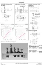
Accessories Connecting dimensions for special clamping arms Double clamping arm, complete Contact bolt – M 6 x 45 Part no. 3614 138 Clamping arm - blank Part no. 3548 900 12 Clamping arm assembly, complete max. 350 bar Clamping force diagram Clamping force diagram Effective clamping force FSp [kN] Effective clamping force FSp [kN] Arrangement of the different connecting types Tube male stud coupling for G1/8 Part no. ND [bar] Designation 9208 075 250 D 8L G 1/8 ED 9208 164 500 D 8S G 1/8 ED Thread reducing adaptor ND [bar] Designation 400 GWR 1/8 –1/4 Actual issue see www.roemheld-usa.com
Open the catalog to page 4All ROEMHELD NORTH AMERICA catalogs and technical brochures
 Stark Speedy Classic
84 Pages
 drop_zero
4 Pages
 Box jaws
4 Pages
 WS 4.3301
3 Pages
 WS 4.3302
4 Pages
 WS 4.5500
6 Pages
 WS 7.3540
2 Pages
 WS 3.3800
2 Pages
 VarioLine
12 Pages
 Double clamping system DF
8 Pages
 HILMA DS
8 Pages
 HILMA KNC
12 Pages
 WS 1.3080
4 Pages
 WS 1.3070
4 Pages
 WS 1.3020
2 Pages
 WS 5.4502
4 Pages
 WS 5.3570
4 Pages
 WS 5.4600
4 Pages
 WS 5.4501
2 Pages
 STARK.easyclick
13 Pages


