- Catalogs
- RobustMotion—Foshan Augmented Intelligence Technol
- RM-MGBD MICRO GRIPPER - DOUBLE CLAWS
RM-MGBD MICRO GRIPPER - DOUBLE CLAWS
1 /56Pages
RM-MGBD MICRO GRIPPER - DOUBLE CLAWS
1 /56Pages
Catalog excerpts

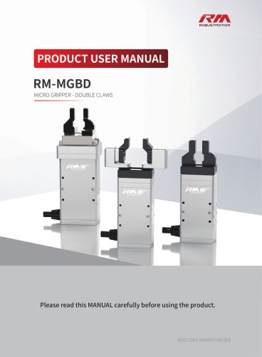
PRODUCT USER MANUAL MICRO GRIPPER - DOUBLE CLAWS Please read this MANUAL carefully before using the product.
Open the catalog to page 1
The RM-MGBD Micro Gripper - Double Claws, with its compact size and powerful capabilities, has become a valuable asset in industrial automation. It boasts numerous significant advantages such as miniature dimensions, low force output, high-speed opening and closing, high precision, high reliability, and simple control. It can seamlessly integrate with major domestic and international brands of industrial robots, collaborative robots, single-axis or multi-axis equipment modules, enabling adaptive gripping of items of various sizes and shapes, and accomplishing processes like holding, transporting,...
Open the catalog to page 2
5.2.5 Trigger Error Reset/Servo Toggle/Command Stop/Force Reset(Precision Torque Control)/Initialize/Execute
Open the catalog to page 4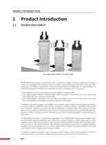
PRODUCT INTRODUCTION Product Introduction Product Description RM-MGBD MICRO GRIPPER - DOUBLE CLAWS The RM-MGBD Micro Gripper - Double Claws offers a closing stroke range of 0-20mm, a gripping force range of 0-30N, and a repeatability positioning accuracy of ±0.02mm, with the fastest open/close time of 0.25s each. With its high precision, efficiency, and reliability, it enhances the performance and effectiveness of industrial robots and automated equipment, providing more convenience and value to integrators and end customers. The RM-MGBD has two main working modes to adapt to different clamping...
Open the catalog to page 5
PRODUCT INTRODUCTION
Open the catalog to page 6
DEBUGGING PREPARATIONS Please check the "Sales Dispatch Note" in the packaging box to confirm whether it corresponds with the product model and quantity received. Sales Dispatch Note Shipping Date: 2022-08-08 Document Number: xxxx xxxx Remarks: xxx Customer Name: xxx Co., Ltd. Attn: Zhang Xiaoming Phone: xxx xxxx xxxx Address: Beijing City xxx xxx xxxx The RM-MGBD Micro Gripper - Double Claws series with a separate (externally mounted) controller is recommended to be matched with the RM-CEP integrated drive and servo controller. Users can select the appropriate protocol model based on the actual...
Open the catalog to page 7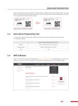
DEBUGGING PREPARATIONS Please check whether the serial numbers on the label of the controller and the electric gripper match. The model of the controller must exactly match the model of the actuator and should not be used interchangeably; otherwise, it may cause abnormal operation of the actuator. DEBUGGING PREPARATIONS Match Model Label on the RM Actuator2.3 Extra Items Prepared by User 1. Output power supply: DC24V±10% / DC48V±10%. Please refer to the controller label for rated current. Please visit the official website of RobustMotion (www.rmaxis.com/en) Download page to download the software,...
Open the catalog to page 8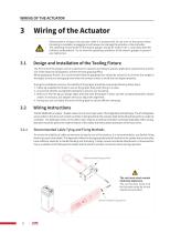
Design and Installation of the Tooling Fixture • Please perform wiring on the actuator while it is powered off. Do not turn on the power before the wiring is complete, as plugging in with power can damage the actuator or the controller. • The operating environment for the electric gripper should be within 0-40 ° C and below 85% RH (without condensation). Try to meet the operating conditions of the electric gripper to prevent any malfunction. The front end of the gripper can be customized or replaced according to specific application requirements and the size of the object to be gripped to achieve...
Open the catalog to page 9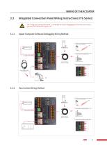
The "integrated connection panel" is intended for quick debugging by first-time users and is generally not required for regular use. © The connector can be cut off without needing to match it with a female plug during use. ©Wire the cable according to the cable labels or the following wiring sequence instructions. 3.3.2 Bus Control Wiring Method ® Tighten the aviation plug and keep the connector and the actuator being stable. ©The connector can be cut off without needing to match it with a female plug during use.
Open the catalog to page 10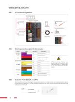
Wire Sequence Description for the Actuator Group Different batches of cables may cause slight differences in the color of the wire core. Please refer to the actual color of the cable for details. After completing the required wiring, for any unused loose wires, it is imperative to use insulating electrical tape or insulating heat shrink tubing to provide insulation protection for the loose wires to prevent accidental contact that could cause a short circuit. Heat shrink tubing
Open the catalog to page 11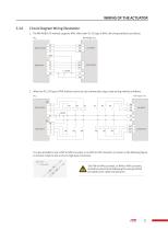
Circuit Diagram Wiring Illustration 1. The RM-MGBD-ITG natively supports NPN. When the PLC I/O type is NPN, the wiring method is as follows: PLC 2. When the PLC I/O type is PNP, indirect control can be achieved by using a relay wiring method as follows: It is also possible to use a PNP to NPN converter or an NPN to PNP converter (as shown in the following figure) to achieve a high-to-low or low-to-high level conversion. NPN to PNP The PNP to NPN converter, or NPN to PNP converter, should be wired strictly following the wiring method provided by the cable manufacturer.
Open the catalog to page 12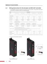
RM-CEP Drive-and-control Integrated Controller (Match Standard Electric Actuator) SoftForce® Integrated Controller (Match SoftForce® Electric Actuator)
Open the catalog to page 13
3.5.1 Wiring Instructions for RM-CEP-X-ECAT Controller Model When using the RM-CEP-X-ECAT model controller, the port definitions are as follows: EtherCAT OUT • CN8 and CN9 do not support for blind plugging. • When using, please connect the upper computer to CN9/ CN8 with a Category 6 Ethernet cable. Modbus RTU Factory-supplied USB to RS485 debugging adapter When using RMS Software for debugging, please use the factory-supplied USB to RS485 debugging adapter to connect to the computer or industrial control computer used for debugging. If connecting to a programmable controller or motion control...
Open the catalog to page 14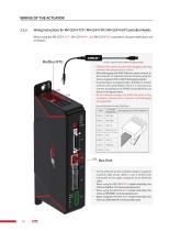
Wiring Instructions for RM-CEP-X-TCP / RM-CEP-X-PN / RM-CEP-X-EIP Controller ModelsWhen using the RM-CEP-X-TCP , RM-CEP-X-PN , and RM-CEP-X-EIP controllers, the port definitions are as follows: Modbus RTU 'Factory-supplied USB to RS485 debugging adapter • CN8 and CN9 support for port blind plugging, allowing insertion into any port of your choice. • When debugging with RMS Software, please connect to the computer or industrial control machine using the factory-supplied USB to RS485 debugging adapter. • If connecting to a programmable controller or motion control card using Modbus RTU, it is necessary...
Open the catalog to page 15All RobustMotion—Foshan Augmented Intelligence Technol catalogs and technical brochures
 RM-GB SERVO GRIPPER
59 Pages
 SoftForce® 3.0
58 Pages