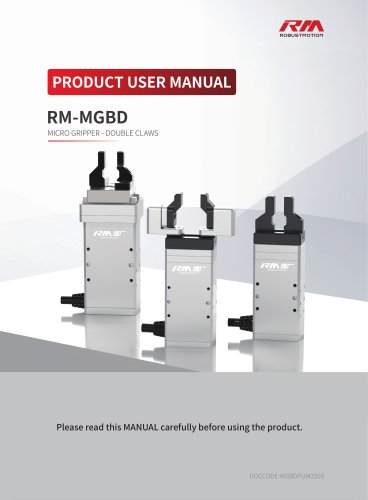
- Catalogs
- RobustMotion—Foshan Augmented Intelligence Technol
- RM-GB SERVO GRIPPER

RM-GB SERVO GRIPPER
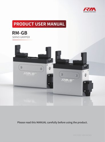
RM-GB SERVO GRIPPER
1. Power Supply: DC24±10%
2. I/O Control: Supported across all models
3. Pulse Control: Supported in most models except one
4. Bus Control: Various protocols supported including Modbus RTU, Modbus TCP, CANopen, PROFINET, EtherNet/IP, and EtherCAT
5. I/O Interface: Optocoupler isolation, 4 input and 4 output ports, supports PNP and NPN
6. Max Input Pulse Frequency: 200KPPS (24V) / 500KPPS (5V)
7. LED Display: Red, Yellow, and Green status lights
8. Dimensions: 190*36*80 mm
9. Weight: 0.323 kg
10. Protection Class: IP20
11. Cooling: Natural Convection Cooling
1. Temperature for Use: 0-40℃
2. Humidity for Use: 85% RH or below (no condensation)
3. Avoid environments with strong light sources, ultraviolet, or corrosive gas
4. Temperature for Preservation: -10℃ to 65℃
5. Humidity for Preservation: 90% RH or below (no condensation)
1. Actuator and Controller Connection: Detailed pinout definitions for various ports (CN5, CN8, CN9)
2. Bus Control Wiring: Instructions for connecting using Modbus RTU, CANopen, and other protocols
3. I/O Control Wiring: Instructions for enabling I/O control and pulse control using dip switches and CN6 port
4. Pulse Control Wiring: Instructions for setting up pulse control, including direction and count control
5. Power Supply Module Wiring: Ensure proper short-circuiting of EMG-KM1 and EMG-KM2 for 24V power supply
1. Software Operation: Download from RobustMotion website, set motion commands, modify parameters
2. Device Connection: Supports Modbus RTU and Modbus TCP, detailed connection instructions provided
3. Main Interface Functions: Includes command editor, parameter editor, I/O mapping, offline data collection, and version info
- Rapid Positioning: The document provides examples of using the [Absolute Move] and [Relative Move] commands to adjust the position of the RM-GB-11-20 gripper. For [Absolute Move], the position is set to 0mm, velocity to 80mm/s, acceleration/deceleration to 500mm/s², and band to 0.1mm. For [Relative Move], the distance is adjusted based on the current and target positions, with similar settings for velocity and acceleration.
- Rapid Flexible Pushing and Pressing: This section describes using a combination of [Absolute Move] and [Push] commands to grip a workpiece. The [Absolute Move] command is used to position the gripper close to the workpiece, and the [Push] command applies additional force to ensure a secure grip.
- Data Collection Settings: The interface allows for real-time data collection, including current position, output, and force. Data can be exported to Excel for analysis.
- Data Collection Commands: Commands include [Start Current Collect], [Start Persistence Collect], and [Execute Command and Collect], which gather data during specific command executions.
- Left Side Status Bar: Displays the current action execution status of the motor, indicating whether commands like [Absolute Move] or [Push] have been completed successfully.
- Right Side Status Bar: Shows the status of external I/O inputs and outputs, useful for troubleshooting I/O control issues.
- Change Station Number & Baudrate: Users can modify the controller's station address and baudrate settings via the Modbus RTU connection.
- Change MAC Address: Each device on the bus requires a unique MAC address, which can be set through the Parameter Editor.
- Change IP Address: For Modbus TCP communication, the controller's IP address can be changed similarly.
- External I/O Input and Output Configuration: Users can configure I/O mappings within the controller to match their specific needs.
- Current Position/Velocity/Torque: Use function code 03 to read holding registers. Example: Reading current torque from address 2154.
- Alarm Signals: Use function code 02 to read input status, such as current alarm status from address 0.
- Positioning Parameters: Use function code 10 for writing multiple registers. Example: Writing a floating-point number requires conversion to hexadecimal and endian conversion.
- Trigger Actions: Use function code 05 to force a coil, such as triggering an error reset.
- Introduction: Requires parameters like distance, acceleration, and velocity before writing the target position.
- Execution: Actions are triggered based on differential detection of written values versus current values.
- Example: Setting parameters for "Absolute Move" and "Pressing Motion" with specific velocity, acceleration, and torque values.
- Data Types: Ensure correct data types to avoid improper parsing.
- Position Verification: Compare current and target positions with a deviation of ±0.1mm and velocity below 2mm/s.
- Torque Mode: Judgments based on position deviation and velocity thresholds.
- Safety Factor: Affects torque percentage to prevent damage.
- Interruption Handling: Optimization measures for command interruptions.
1. Initialize Interrupt: When interrupted by an Initialize command, wait for the completion signal, then update the position register with the current actuator position.
2. Stop or Servo Toggle Interrupt: Introduce a 15-30ms delay for stability, then update the position register with the current actuator position.
1. General Principles: Apply WD-40 lubricant if the actuator hasn't been used for over half a month, especially in winter.
2. First Time Use: Use WD-40 on unused travel ranges.
3. Long Term Non-use: Use WD-40 only in specific situations; for regular maintenance, use NSL grease.
4. Maintenance Frequency: Regular checks and grease replenishment are recommended at specified intervals (1 month, 6 months, 1 year, and every half year thereafter).
1. Grease Replenishment: RM-GB series require grease every 100,000 operations or every six months.
2. Dust Cover Replacement: Replace if damaged to avoid affecting actuator life.
3. External Cleaning and Lubrication: Regular cleaning and lubrication are advised to maintain performance and extend service life.
1. Usage Risk Warning: Follow operating procedures to minimize risks.
2. Disclaimer: No liability for damages from misuse, unauthorized modifications, or third-party services.
3. Intellectual Property: Products and trademarks are protected by law.
4. Quality Guarantee: Covers manufacturing defects, not improper use or environmental damage.
5. Applicable Law: Governed by Chinese law, disputes resolved through negotiation or court.
6. Modifications: Company reserves the right to update products and disclaimers.
Catalog excerpts

PRODUCT USER MANUAL SERVO GRIPPER Please read this MANUAL carefully before using the product.
Open the catalog to page 1
RM-GB servo gripper is a mature and widely used intelligent electric gripper, featuring significant advantages such as high rigidity, high load capacity, high precision, high reliability, and simple control. It offers a variety of stroke options, ranging from mini to heavy-duty, and is available in multiple specifications and models to meet diverse requirements. RM-GB servo gripper is compatible with industrial robots, collaborative robots, and single or multi-axis equipment modules from various domestic and international brands, capable of performing various industrial operations such as clamping,...
Open the catalog to page 2
5.2.5 Trigger Error Reset/Servo Toggle/Command Stop/Force Reset(Precision Torque Control)/Initialize/Execute
Open the catalog to page 4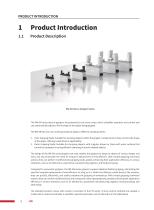
PRODUCT INTRODUCTION Product Introduction Product Description RM-GB (Servo Gripper) Series The RM-GB series electric grippers are powered by one servo motor, which simplifies operation and control and can automatically adjust to fit the shape of the object being gripped. The RM-GB has two main working modes to adapt to different clamping needs: 1. Inner Gripping Mode: Suitable for clamping objects within the gripper's stroke band, it does not limit the shape of the object, offering a wide band of applicability. 2. Outer Gripping Mode: Suitable for clamping objects with irregular shapes or those...
Open the catalog to page 5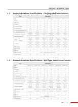
PRODUCT INTRODUCTION
Open the catalog to page 6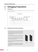
DEBUGGING PREPARATIONS Please check the "Sales Dispatch Note" in the packaging box to confirm whether it corresponds with the product model and quantity received. Sales Dispatch Note Shipping Date: 2022-08-08 Document Number: xxxx xxxx Remarks: xxx Customer Name: xxx Co., Ltd. Attn: Zhang Xiaoming Phone: xxx xxxx xxxx Address: Beijing City xxx xxx xxxx The RM-GB Servo Gripper series with a separate (externally mounted) controller is recommended to be matched with the RM-CEP integrated drive and servo controller. Users can select the appropriate protocol model based on the actual bus protocol...
Open the catalog to page 7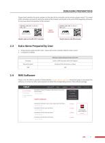
DEBUGGING PREPARATIONS Please check whether the serial numbers on the label of the controller and the electric gripper match. The model of the controller must exactly match the model of the actuator and should not be used interchangeably; otherwise, it may cause abnormal operation of the actuator. DEBUGGING PREPARATIONS Match Model Label on the RM Actuator2.3 Extra Items Prepared by User 1. Output power supply: DC24V±10% . Please refer to the controller label for rated current. Please visit the official website of RobustMotion (www.rmaxis.com/en) Download page to download the software, or contact...
Open the catalog to page 8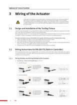
Design and Installation of the Tooling Fixture • Please perform wiring on the actuator while it is powered off. Do not turn on the power before the wiring is complete, as plugging in with power can damage the actuator or the controller. • The operating environment for the electric gripper should be within 0-40° C and below 85% RH (without condensation). Try to meet the operating conditions of the electric gripper to prevent any malfunction. The front end of the gripper can be customized or replaced according to specific application requirements and the size of the object to be gripped to achieve...
Open the catalog to page 9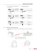
WIRING OF THE ACTUATOR 2. Bottom Wiring - Optional Wiring Methods A / H / V A - Aviation Plug SW (Note: RM-GB-11-20-ITG models cannot be selected with bottom wiring.) It can be rotated in four directions at 90 degrees along the fixed surface. H - Horizontal Wiring It can be rotated in four directions at 90 degrees along the fixed surface. V - Vertical Wiring It can be rotated in four directions at 90 degrees along the fixed surface. Wiring Instructions for the Actuator 1. Cable Tying Method with Extension Cables on the Body (Using the A-Type Aviation Plug SW as an Example) The red area must be...
Open the catalog to page 10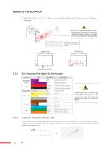
2. Cable Tying Method with Fixed Connectors on the Body (Using the H-Type Horizontal Wiring as an Example) The red area must be fixed properly. The connector and actuator must be in a relatively stationary state to prevent the internal cables from being pulled, which could cause a short circuit. Bottom Fixing Middle Fixing 3.2.3 Wire Sequence Description for the Actuator Group Different batches of cables may cause slight differences in the color of the wire core. Please refer to the actual color of the cable for details. 3.2.4 Insulation Protection of Loose Wire After completing the required...
Open the catalog to page 11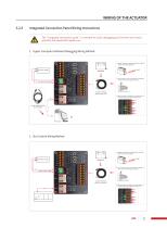
The "integrated connection panel" is intended for quick debugging by first-time users and is generally not required for regular use. Use the matching cable for connection © Tighten the aviation plug and keep the connector and the actuator being stable. © The co n nector canbecutoffwithoutneedingto match it with a female plug during use. ©Wire the cable according to the cable labels or the following wiring sequence instructions. 2. Bus Control Wiring Method © The co n nector canbecutoffwithoutneedingto match it with a female plug during use. © Wire the cable according to the cable labels or thefollowingwiringsequencei...
Open the catalog to page 12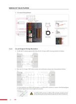
3. I/O Control Wiring Method © Tighten the aviation plug and keep the connector and the actuator being stable. D Th e co n nector ca n be cut off without need i ng to match it with a female plug during use. 1. The RM-GB-ITG natively supports NPN. When the PLC I/O type is NPN, the wiring method is as follows: It is also possible to use a PNP to NPN converter or an NPN to PNP converter (as shown in the following figure) to achieve a high-to-low or low-to-high level conversion. A The PNP to NPN converter, or NPN to PNP converter, should be wired strictly following the wiring method provided by the...
Open the catalog to page 13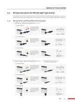
Wiring Instructions for RM-GB (Split-Type Series) Wiring Position and Wiring Method of the Actuator The split-type series refers to actuators that require an external drive and control integrated controller for support of a variety of bus communication methods. Below is an introduction to the wiring methods that match different controllers. 1. Side Wiring - Optional Wiring Methods A / H / V S - Switched Wiring It can be rotated in four directions at 90 degrees along the fixed surface. It can be rotated in four directions at 90 degrees along the fixed surface. V - Vertical Wiring It can be rotated...
Open the catalog to page 14All RobustMotion—Foshan Augmented Intelligence Technol catalogs and technical brochures
 SoftForce® 3.0
58 Pages