

- Products
- Catalogs
- News & Trends
- Exhibitions
SpinCoTM_SP3D01_07

SpinCoTM_SP3D01_07
- Capable of operating at speeds up to 55,000 rpm.
- Provides 50 to 556 sin/cos periods per revolution.
- Delivers ABZ digital incremental outputs with up to 4,096 steps per sin/cos period.
- Includes analogue output signals (1 Vpp) and IP67 protection.
- Compact readhead size with high accuracy.
- System data includes pole lengths of 1 mm or 2 mm, with less than 1 electrical degree of hysteresis.
- Electrical data specifies a supply voltage of 5 V ±10% and a current consumption of less than 50 mA.
- Environmental data covers operating temperatures from -40 °C to +85 °C and IP67 sealing.
Catalog excerpts

DATA SHEET SP3D01_07 Issue 7, 25th October 2023 SpinCoTM Incremental Magnetic Encoder System SPINDLE ENCODER SpinCo is an incremental magnetic encoder system designed for use as primary position and speed feedback sensor for machine tool spindles. HIGH SPEED It consists of two key elements, a readhead and a magnetic ring. RLS proven AMR and GMR sensor technologies are used for sensing magnetized pattern on the magnetic ring to ensure accurate and reliable operation over the entire operating range. ROBUST DESIGN Signal stability From 50 to 556 sin/cos periods per revolution ABZ digital incremental outputs with up to 4,096 steps per sin/cos period Wide installation tolerances Small readhead size Analogue output signals (1 Vpp) High accuracy INDUSTRIAL AUTOMATION HARSH ENVIRONMENT MOTOR CONTROL
Open the catalog to page 1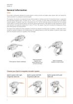
General information The encoder continuously calibrates the sensed signals to ensure accurate and reliable output signals, which are reported as industry standard 1 Vpp analogue incremental signals. The magnetic ring consists of an elastoferrite layer firmly bonded to a stainless steel hub. The elastoferrite layer is magnetised with alternating magnetic poles. The poles can be 1 mm or 2 mm long. To ensure safety and reliability even at the highest rotational speeds, all magnetic rings have a fully welded cover foil. This thin steel layer protects the elastoferrite from damage and the effects...
Open the catalog to page 2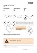
Storage and handling Storage temperature Operating temperature ߌ High resistance to humidity HANDLE WITH CARE. This encoder system is a high performance metrology product and should be handled with the same care as any other precision instrument. The use of industrial tools such as hammers and chisels or exposure to strong magnets such as a magnetic base is unacceptable and carries the risk of irreparable damage to the product. The magnetic ring should not be exposed to magnetic field densities higher than 25 mT on its surface, as this can damage the ring. Exposure to external magnetic fields...
Open the catalog to page 3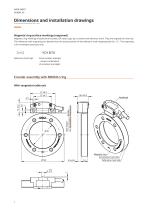
Dimensions and installation drawings Dimensions and tolerances are in mm. Magnetic ring surface markings (engraved) Magnetic ring markings include serial number, QR code, logo, part number and reference mark. They are engraved on the hub. The reference mark engraving can deviate from the actual position of the reference mark magnetization for ±5 °. The engraving is for orientation purposes only. YD1B70 Reference mark sign Serial number example - unique combination of six letters and digits Encoder assembly with MR063U ring With tangential cable exit 37 ±0.2 16.5 ±0.2 Ride height Magnetic ring...
Open the catalog to page 4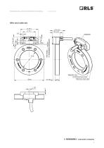
Dimensions and installation drawings With axial cable exit 37 ±0.2 Ride height Magnetic ring Incremental track side 4.5 ±0.5 Reference mark side Pole length
Open the catalog to page 5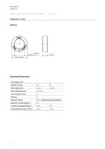
Dimensions and installation drawings Technical features Maximum speed Refer to Maximum speed calculator
Open the catalog to page 6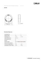
Dimensions and installation drawings Technical features Pole length (mm) Maximum speed Refer to Maximum speed calculator Moment of inertia (kgmm )
Open the catalog to page 7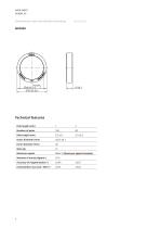
Dimensions and installation drawings Technical features Pole length (mm) Maximum speed Refer to Maximum speed calculator Moment of inertia (kgmm )
Open the catalog to page 8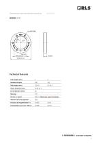
Dimensions and installation drawings Technical features Pole length (mm) Maximum speed Refer to Maximum speed calculator Moment of inertia (kgmm )
Open the catalog to page 9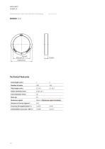
Dimensions and installation drawings Technical features Pole length (mm) Maximum speed Refer to Maximum speed calculator Moment of inertia (kgmm )
Open the catalog to page 10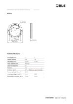
Dimensions and installation drawings Technical features Pole length (mm) Maximum speed Refer to Maximum speed calculator Moment of inertia (kgmm )
Open the catalog to page 11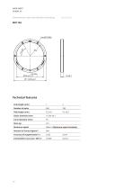
Dimensions and installation drawings Technical features Pole length (mm) Maximum speed Refer to Maximum speed calculator Moment of inertia (kgmm )
Open the catalog to page 12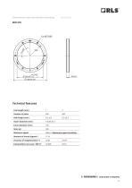
Dimensions and installation drawings Technical features Pole length (mm) Maximum speed Refer to Maximum speed calculator Moment of inertia (kgmm )
Open the catalog to page 13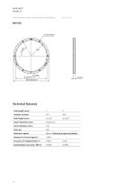
Dimensions and installation drawings Technical features Pole length (mm) Maximum speed Refer to Maximum speed calculator Moment of inertia (kgmm )
Open the catalog to page 14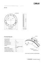
Dimensions and installation drawings Maximum speed Refer to Maximum speed calculator Magnetic ring Incremental track side Reference mark side See the encoder assembly on the follo
Open the catalog to page 15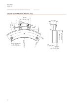
Dimensions and installation drawings Encoder assembly with MR176X ring 37 ±0.2 4.3
Open the catalog to page 16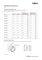
Installation instructions Installation of magnetic rings Machine the mounting shaft according to the dimensions given in the table below. Dimensions and tolerances are in mm. Shaft diameter (clearance fit installation, fasteners, gluing) - Ds Shaft outer diameter (press fit or shrinkage press fit) - Dspd 20 r6 Installation by press-fitting Slip the ring onto the mating shaft applying equal or uniform force along the whole ring circumference. Shaft* Magnetised ring
Open the catalog to page 17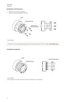
Installation with fasteners 1. 2. Slide the ring onto the mating shaft. Attach the ring with appropriate fasteners. Magnetised ring Shaft* Magnetised ring See table of recommended tightening torques for RLS products (document TTD01) available at RLS media center. * Not provided. ** For the depth of the groove, please check the specifications of the adhesive. Shaft* Magnetised ring Magnetised ring
Open the catalog to page 18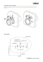
Installation of the readhead Please use the supplied spacer for optimum ride height. For proper mounting, a mounting base should be made prior to installation. Drawing created. Mounting base Mounting surface Shaft center
Open the catalog to page 19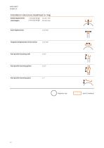
Installation tolerances (readhead to ring) Radial displacement (ride height) 1 mm pole length 2 mm pole length Axial displacement Tangential displacement of the sensor Non-parallel mounting (roll) Non-parallel mounting (pitch) Magnetic ring
Open the catalog to page 20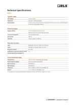
Technical specifications System data Pole length Less than 1 electrical degree Less than ±2 counts for maximum interpolation factor and less than unit of resolution for all other interpolation factors Electrical data Supply voltage 5 V ±10 % (absolute maximum 6 V) Reverse polarity and overvoltage protected Current consumption Set-up time Mechanical data Mass Readhead: 120 g (1 m cable, no connector) Coefficient of thermal expansion (CTE) of steel hub of the ring (ppm/°C) Environmental data Temperature Environmental sealing * IP protection is only guaranteed when suitable connector with same or...
Open the catalog to page 21All RLS catalogs and technical brochures
 Artos_DRD01_03
21 Pages
 RE58_RE58D04_04
22 Pages
 RE22_RE22D01_10
9 Pages
 RM22_RM22D01_05
9 Pages
 MR_MR01D01_06
55 Pages
 MR_MR02D02_04
41 Pages
 LM13_LM13D01_13
17 Pages
 LM10 Series
20 Pages
 AksIM-2_MBD07_05
14 Pages
 RE16 / RM16
15 Pages
 AksIM-2_MBD01_11
53 Pages
 FlexINTM
2 Pages
 OnAxis™ Redundant_RDD01_01
14 Pages
 Orbis™
2 Pages
 DRD01_03
21 Pages
 SARD01_02
15 Pages
 DBD01_05
21 Pages
 MS Incremental Magnetic Scales
26 Pages
 AksIM-4
14 Pages


- Angular encoder
- Incremental encoder
- Incremental rotary encoder
- Absolute rotary encoder
- Industrial rotary encoder
- Magnetic rotary encoder
- DC rotary encoder
- IP67 rotary encoder
- Compact rotary encoder
- Aluminum rotary encoder
- Stainless steel rotary encoder
- Linear encoder
- Ultra-rugged rotary encoder
- SSI angular encoder
- Digital rotary encoder
- 5VDC rotary encoder
- Incremental linear encoder
- High-accuracy rotary encoder
- RS-422 rotary encoder
- Miniature rotary encoder