
Catalog excerpts
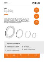
DATA SHEET SARD01_02 Issue 02, 21st June 2024 SAR Solid Absolute Magnetic Rings COMPACT AND ROBUST DESIGN VARIOUS SIZES Absolute radial magnetic rings are compatible with the ArtosTM readhead and are suitable for most demanding applications. The robust design protects the magnetic ring against the ingress of liquids and high temperatures, so that it remains undamaged even in extremely contaminated and hot environments. HIGH SPEED AND TEMPERATURE Compatible with ArtosTM readhead Easy mounting Excellent resistance to common machine tool contaminants High operating speed Various sizes of diameters available Operation at high temperatures MACHINE TOOL ASSEMBLY LINES INDUSTRIAL AUTOMATION
Open the catalog to page 1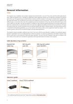
General information The magnetic ring is available in two versions: exposed and protected with a cover foil. The version with the visible elasto-ferrite layer, called the exposed ring, is intended for applications where aggressive liquids are not expected to damage the sensitive part of the ring. The exposed ring can withstand dust, moisture and dirt. However if a thin layer of stainless steel is applied over the elasto-ferrite layer, the ring becomes more robust and suitable for harsh environments. The cover foil can be applied in two different ways. In one variant, the cover foil is...
Open the catalog to page 2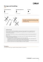
Storage and handling Storage temperature Operating temperature The magnetic ring should not be exposed to magnetic field densities higher than 25 mT on its surface, as this can damage the ring. HANDLE WITH CARE The use of industrial tools during installation or exposure to strong magnets such as a magnetic base is not recommended as it carries the risk of damaging parts of the system which as a result might not perform in accordance with specifications. Use of tools such as drift, punch or similar are expressly forbidden and should not be used during installation to adjust run-out. Improper...
Open the catalog to page 3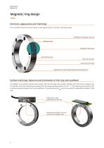
Magnetic ring design Structure, appearance and markings The incremental track of the ring is always on the engraving side, as shown in the figure below. OPTIONAL: Protective cover foil Absolute track Magnetic field viewer Incremental track Elasto-ferrite layer Stainless steel flange Absolute zero mark engraving with positioning hole Surface markings, features and orientation of the ring and readhead All magnetic ring markings include serial number, QR code, RLS logo, part number, absolute zero mark and no-magnet sign. The absolute zero mark engraving can deviate from the actual absolute...
Open the catalog to page 4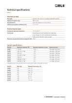
Technical specifications Mechanical data Ring types Exposed / with cover foil / completely sealed IP67 (welded) Material of magnetic layer Ring dimensions From outer diameter 57 mm to 478 mm Hub thermal expansion coefficient (CTE) Environmental data Storage and operating temperature Sealing type Exposed type: dirt, dust, humidity (non-condensing) Cover foil type: dirt, dust, humidity (non-condensing) Sealed version: IP67 (oils, coolant, grease) Maximum non-operational external magnetic field 25 mT System specifications Ring PN Maximum resolution in arcsec System accuracy * * Installation...
Open the catalog to page 5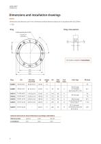
Dimensions and installation drawings Dimensions and tolerances are in mm. Dimensions without tolerance values are in accordance with ISOID2768-m. HD OD Ring cross-section N holes equally spaced on 3D models available on RLS website. OD (with cover foil) Hole Type General tolerances for linear dimensions according to ISO 2768 m Tolerance class M4 through counterbore both sides 7.2 M5 through M6 through counterbore top side 10.5 6.5 5.5 through counterbore top side 10 5.4
Open the catalog to page 6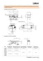
The orientation of the readhead and ring is essential. The engraved side of the ring and readhead must match for the orientation to be correct. 58 Installation with housed readhead Tangential offset (ring) 29 ±T 5 Tangential offset Optical centerline (ring) Installation withTangential PCB-A readhead offset Lateral offset (L) / axial offset Magnet ring SARXXX Tangential (T) / centerline offset Recommended ride height / radial offset 1 Ride height (RH) / radial offset (with cover foil) (6 : 4) 0.1 to 0.5 mm Ride height (RH) / radial offset 0 Tangential offset
Open the catalog to page 7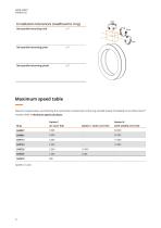
Installation tolerances (readhead to ring) Non-parallel mounting (roll) Non-parallel mounting (pitch) Maximum speed table Maximum speed values are limited by the mechanical characteristics of the ring and ABZ output (if enabled) on the PCB-A ArtosTM module. Refer to Maximum speed calculator. Option E Option C (with cover foil) (with welded cover foil)
Open the catalog to page 8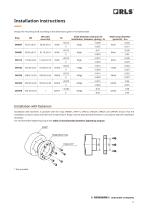
Installation instructions Shaft outer diameter (press-fit) - Dspd Design the mounting shaft according to the dimensions given in the table below. Shaft* OD (with Shaft diameter (clearance fit Ring OD ID cover foil) installation, fasteners, gluing) - Ds Magnetized ring +0.016 –0.009 SAR057 56.70 ±0.01 56.90 ±0.10 45H6 45g6 0 –0.025 Installation with fasteners Installation with fasteners is possible with the rings SAR081, SAR114, SAR162, SAR229, SAR325 and SAR478. Ensure that the installation surface is clean and free from contamination. Rings must be attached with fasteners in accordance...
Open the catalog to page 9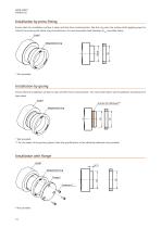
Installation by press-fitting Ensure that the installation surface is clean and free from contamination. Slip the ring onto the mating shaft applying equal or uniform force along the whole ring circumference. For recommended shaft diameter (Dspd) see table above. Shaft* Magnetized ring Magnetized ring Magnetized Ensure that the installation surface is cleanring and free from contamination. For more information see the adhesive manufacturer’s data sheet. Groove for adhesive** Magnetized ring Shaft* Magnetized ring Mounting part* Flange* Fasteners* Magnetized ring M4 fasteners Installation...
Open the catalog to page 10
Readhead installation with a dedicated installation tool A special installation tool can be supplied for easier, more reliable and time-saving installation of the readhead in relation to the ring. The installation tool limits the readhead in 6 directions (ride height/radial offset, centerline/tangential, yaw, axial/lateral, pitch and roll offset) and thus ensures precise alignment of the readhead, guaranteeing optimal performance. A dedicated mounting tool is required for each SAR ring to adjust the diameter of the ring. Please check the part number diagram to select the correct...
Open the catalog to page 11All RLS catalogs and technical brochures
-
ArtosTM_DBD01_05
21 Pages
-
Artos_DRD01_03
21 Pages
-
RE58_RE58D04_04
22 Pages
-
RE22_RE22D01_10
9 Pages
-
RM22_RM22D01_05
9 Pages
-
MR_MR01D01_06
55 Pages
-
MR_MR02D02_04
41 Pages
-
LM13_LM13D01_13
17 Pages
-
LM10 Series
20 Pages
-
AksIM-2_MBD07_05
14 Pages
-
RE16 / RM16
15 Pages
-
SpinCoTM_SP3D01_07
31 Pages
-
AksIM-2_MBD01_11
53 Pages
-
FlexINTM
2 Pages
-
OnAxis™ Redundant_RDD01_01
14 Pages
-
Orbis™
2 Pages
-
DRD01_03
21 Pages
-
ArtosTM_DBD01_05
21 Pages
-
MS Incremental Magnetic Scales
26 Pages
-
AksIM-4
14 Pages


