RE58_RE58D04_04
1 /22Pages

RE58_RE58D04_04
1 /22Pages
Catalog excerpts

DATA SHEET RE58D04_04 Issue 4, 30th June 2023 EXCELLENT PRICE PERFORMANCE RATIO RE58 Rotary Magnetic Shaft Encoder HIGHLY RELIABLE The RE58 is a robust industrial standard rotary magnetic encoder consisting of two parts: the RM44 magnetic encoder and various 58 mm flanges. The solid metal housing of the RM44 encoder offers the highest IP protection class, high EMC immunity, an extended operating temperature range and the best possible shock and vibration resistance. EASY TO REPLACE PARTS Robust modular design Industry standard absolute, incremental and analogue output options High reliability from proven non-contact encoder technology Excellent price-performance INDUSTRIAL AUTOMATION ASSEMBLY LINES HARSH ENVIRONMENT GREEN ENERG
Open the catalog to page 1
General information The RE58 is an encoder for measuring shaft position. A magnet is mounted within the mounting flange. Rotation of this magnet is sensed by the RM44 encoder. The output signals are provided in industry standard absolute, incremental and analogue sinusoidal formats. Available are resolutions of up to 13 bit absolute SSI and/or 8,192 counts per revolution incremental for 5 V or 24 V power supply. A system accuracy of ±0.5° can be achieved. RE58 rotary shaft encoder system Mounting flange (available separately) (available separately) Choose your RE58 system The RE58 is a pre-assembled...
Open the catalog to page 2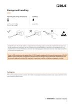
Storage and handling Operating and storage temperature Handle with care. This encoder system is a high performance metrology product and should be handled with the same care as any other precision instrument. The use of industrial tools during installation or exposure to strong magnets such as a magnetic base is not recommended as it carries the risk of damaging parts of the system which as a result might not perform in accordance with specifications. Power to RE58 encoders must be supplied from a DC SELV supply complying with the essential requirements of EN (IEC) 60950 or similar specification....
Open the catalog to page 3
Dimensions and installation drawings Dimensions and tolerances are in mm. RE58-B encoder (with RE58B06 mounting flange) RE58-A encoder (with RE58A10 mounting flange)
Open the catalog to page 4
Dimensions and installation drawings Dimensions and tolerances are in mm. RE58-C encoder (with RE58C10 mounting flange)
Open the catalog to page 5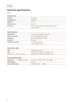
Technical specifications System data Resolution Maximum speed System accuracy Set-up time 100 ms (first data ready after supply voltage is in range), worst case: 200 ms Electrical data Supply voltage Current consumption Output load Flying lead Voltage drop over cable ~13 mV/m (without load) ~54 mV/m (with 120 Ω load) Mechanical data Cable (encoder with 1 m cable, no connector) Environmental data Temperature Environmental sealing
Open the catalog to page 6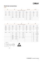
Shield - see connection diagram VA Shield - see connection diagram Vdd Brown/ Black
Open the catalog to page 7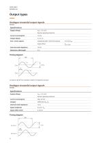
Output types Analogue sinusoidal output signals RE58AC Specifications Supply voltage Vdd = 5 V ±5 % Reverse polarity protection Current consumption Output signals Sine / cosine signals Amplitude (with 120 Ω termination) Signal offset Internal serial impedance Maximum cable length VA leads VB by 90° for clockwise rotation of magnetic actuator. Analogue sinusoidal output signals RE58BC Specifications Supply voltage Vdd = 5 V ±5 % Reverse polarity protection Current consumption Internal serial impedance Signal amplitude Signal offset (Vref)
Open the catalog to page 8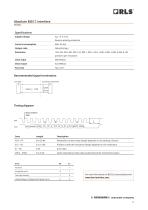
Absolute BiSS C interface RE58DC Specifications Supply voltage Vdd = 5 V ±5 % Reverse polarity protection Current consumption Output code Natural binary Clock input Data output Recommended signal termination Encoder Customer electronics Timing diagram latch position data MA SLO Revolution counter value (length depends on the settings chosen) Position inside the revolution (length depends on the resolution) Error data Cyclic redundancy check data; polynomial 0x43; inverted bit output Amplitude error Undervoltage; Configuration; System error For more information on BiSS C protocol please visit...
Open the catalog to page 9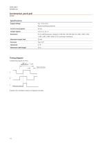
Specifications Supply voltage Vdd = 8 V to 26 V Reverse polarity protection Current consumption Output signals Maximum output load Maximum cable length Timing diagram Complementary signals not shown 360° x 4 = 1 cycle counts per rev Edge separation Reference impulse B leads A for clockwise rotation of magnetic actuat
Open the catalog to page 10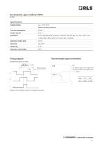
Incremental, open collector NPN RE58IB Specifications Supply voltage Vdd = 8 V to 26 V Reverse polarity protection Current consumption Output signals Maximum output load Maximum cable length Timing diagram Recommended signal termination Complementary signals not shown 360° x 4 = 1 cycle counts per rev R > power supply / max. output load Edge separation R (recommended values: table below) A, B, Z Reference impulse B leads A for clockwise rotation of magnetic actuator.
Open the catalog to page 11
Incremental, RS422 output signal RE58IC Specifications Supply voltage Vdd = 5 V ±5 % Reverse polarity protection Current consumption Output signals Maximum cable length Timing diagram Recommended signal termination Complementary signals not shown Encoder 360° x 4 = 1 cycle counts per rev Edge separation Reference impulse B leads A for clockwise rotation of magnetic actuator. Customer electronics
Open the catalog to page 12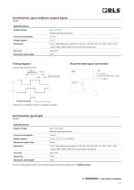
Incremental, open collector output signal RE58IE Specifications Supply voltage Vdd = 5 V ±5 % Reverse polarity protection Current consumption Output signals Maximum cable length Timing diagram Recommended signal termination Complementary signals not shown 360° x 4 = 1 cycle counts per rev Edge separation Reference impulse B leads A for clockwise rotation of magnetic actuator. Specifications Supply voltage Vdd = 8 V to 26 V Reverse polarity protection Current consumption Output signals Maximum output load Maximum cable length For the timing diagram and recommended signal termination please see...
Open the catalog to page 13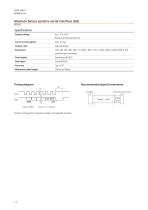
Absolute binary synchro-serial interface (SSI) RE58SC Specifications Supply voltage Vdd = 5 V ±5 % Reverse polarity protection Current consumption Output code Natural binary Data output Data input Maximum cable length Timing diagram Recommended signal termination Encoder Position increases for clockwise rotation of magnetic actuator.
Open the catalog to page 14All RLS catalogs and technical brochures
 Artos_DRD01_03
21 Pages
 RE22_RE22D01_10
9 Pages
 RM22_RM22D01_05
9 Pages
 MR_MR01D01_06
55 Pages
 MR_MR02D02_04
41 Pages
 LM13_LM13D01_13
17 Pages
 LM10 Series
20 Pages
 AksIM-2_MBD07_05
14 Pages
 RE16 / RM16
15 Pages
 SpinCoTM_SP3D01_07
31 Pages
 AksIM-2_MBD01_11
53 Pages
 FlexINTM
2 Pages
 OnAxis™ Redundant_RDD01_01
14 Pages
 Orbis™
2 Pages
 DRD01_03
21 Pages
 SARD01_02
15 Pages
 DBD01_05
21 Pages
 MS Incremental Magnetic Scales
26 Pages
 AksIM-4
14 Pages


- Angular encoder
- Incremental encoder
- Incremental rotary encoder
- Absolute rotary encoder
- Magnetic rotary encoder
- Industrial rotary encoder
- IP67 rotary encoder
- Compact rotary encoder
- DC rotary encoder
- Aluminum rotary encoder
- Stainless steel rotary encoder
- Linear encoder
- Ultra-rugged rotary encoder
- SSI angular encoder
- Digital rotary encoder
- 5VDC rotary encoder
- Incremental linear encoder
- High-accuracy rotary encoder
- Non-contact rotary encoder
- Miniature rotary encoder