
Catalog excerpts

DATA SHEET MSD01_06 Issue 06, 21st May 2024 MS Incremental Magnetic Scales The robust MS incremental magnetic scales consist of a stainless steel carrier and an elastomer-bonded ferrite. The elasto-ferrite layer is magnetised with 2 mm, 2.032 mm or 5 mm long alternating magnetic poles that form an incremental magnetic pattern. DISTANCE CODED REFERENCE MARK Customer selectable position of reference mark Optional protective cover foil for heavy duty applications Four accuracy grades available: ±10 μm/m, ±20 μm/m, ±40 μm/m, ±100 μm/m Excellent resistance to dirt, dust and humidity Partial arc application available Easy installation with adhesive tape, end clamps or track section PRINTING TECHNOLOGY LINEAR MOTOR INDUSTRIAL AUTOMA
Open the catalog to page 1
General information The incremental RLS magnetic scales are compatible with RLS standard LM and component level RoLin readheads, which ensure reliable operation due to the non-contact design. Selection guide Scale width Pole length Compatibility with readheads LM10 Ri - Unique and multiple reference mark or only incremental track available No Ri - No unique and multiple reference mark option, only incremental track available Ri+DCRM - Unique, multiple, distance-coded reference mark or only incremental track available * Compatible with DPI version only. For readhead specifications see data...
Open the catalog to page 2
Storage and handling Storage temperature Operating temperature Scale applied on the linear guide: High resistance to humidity –40 °C to +100 °C Scale applied on the curved surface: –40 °C to +80°C It is strongly recommended that the scale is factory cut at RLS or the product warranty does not apply. The magnetic scale should not be exposed to magnetic field densities higher than 25 mT on its surface, as this may damage the scale. Chemical resistance The use of alcohol for cleaning is considered safe, but it is not allowed to immerse the scale in alcohol. Furthermore, the scale surface print...
Open the catalog to page 3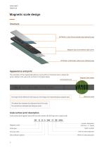
Magnetic scale design Structure OPTIONAL: Cover foil and double-sided adhesive tape Magnetic layer and stainless steel carrier OPTIONAL: VHB Double-sided acrylic adhesive tape Appearance and print The orientation of the magnetised reference mark and the incremental track is always the same, relative to the scale print as shown in the figure below. Incremental track Magnetic field viewer The shape of the reference mark may vary. The image is for representation purposes only. Reference mark The dotted line indicates the reference side of the scale. The vertical line indicatest the reference...
Open the catalog to page 4
Technical specifications Dimensions and tolerances are in mm. Dimensions without tolerance values are in accordance with ISO 2768-m. System data Pole length Reference mark Unique, DCRM, multiple reference marks Scale accuracy* * For more information about the accuracy please see the MST01 technical article at RLS Media center. Mechanical data Material Magnetic scale Double-sided acrylic adhesive tape Cover foil Double-sided tape 1.43 ±0.1 mm (with back adhesive) 1.3 ±0.1 mm (without back adhesive) Cover foil width Maximum length 50 m (150 m with longer lead time**) Length tolerance ±0.5 mm...
Open the catalog to page 5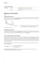
Environmental data Temperature Scale applied on the linear guide: –40 °C to +100 °C Scale applied on the curved surface: –40 °C to +80 °C Reference mark options Unique reference mark The readhead must be ordered with reference mark option A (see corresponding readhead data sheet). The magnetic scale must be ordered with reference mark (see Part numbering). If required, the cover foil can be installed over the reference mark. Magnetised reference mark will have a visible marking. The shape and the position of the magnetised reference mark are critical so these options are only available as...
Open the catalog to page 6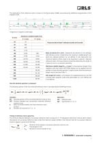
The distribution of the reference marks is shown in the figure below. DCRMs are produced by additional magnetisation of the magnetic scale. K * Depends on magnetic scale length. Maximum codable length (mm) P = 2 mm There must be at least 3 reference marks on the scale. Basic increment (K in mm) - Represents the distance in mm between odd reference marks; it determines the maximum codable length over which the absolute position can be defined. It also determines the minimum distance which needs to be traversed to capture 2 adjacent reference marks. The basic distance should be divisible by...
Open the catalog to page 7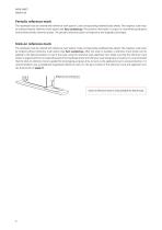
Periodic reference mark The readhead must be ordered with reference mark option C (see corresponding readhead data sheet). The magnetic scale must be ordered without reference mark option (see Part numbering). The position information is output in incremental quadrature format with periodic reference pulses. The periodic reference pulses correspond to the magnetic pole length. Stick-on reference mark The readhead must be ordered with reference mark option A (see corresponding readhead data sheet). The magnetic scale must be ordered without reference mark option (see Part numbering). After...
Open the catalog to page 8
Installation instructions Installation with adhesive tape Applicable for MS05, MS07, MS10, MS12 and MS15 Installation surface preparation Magnetic scales can be equipped with VHB backside adhesive tape. Most substrates are best prepared by cleaning with a 50:50 mixture of isopropyl alcohol and water before applying the magnetic scale. Exceptions to the general procedure that may require additional surface preparation include: ⦁ Heavy oil/grease: To remove heavy oil or grease from a surface, a degreaser or solvent-based cleaning agent may be required, followed by cleaning with IPA/water. ⦁...
Open the catalog to page 9
1. Load the scale into the applicator tool. Separate the backing paper from the first 40 mm of scale and feed the scale into the applicator tool. 2. Apply the scale. Push the scale carefully through to the end of scale mark, ensuring that it does not stick to the mounting surface until it is in position. Attach the end of the scale to the mounting surface with light finger pressure. 3. Ensure complete adhesion. Apply firm finger pressure along the full length of the scale from the centre outwards to each end. To prevent the scale from sticking to the mounting surface during this operation...
Open the catalog to page 10All RLS catalogs and technical brochures
-
ArtosTM_DBD01_05
21 Pages
-
Artos_DRD01_03
21 Pages
-
RE58_RE58D04_04
22 Pages
-
RE22_RE22D01_10
9 Pages
-
RM22_RM22D01_05
9 Pages
-
MR_MR01D01_06
55 Pages
-
MR_MR02D02_04
41 Pages
-
LM13_LM13D01_13
17 Pages
-
LM10 Series
20 Pages
-
AksIM-2_MBD07_05
14 Pages
-
RE16 / RM16
15 Pages
-
SpinCoTM_SP3D01_07
31 Pages
-
AksIM-2_MBD01_11
53 Pages
-
FlexINTM
2 Pages
-
OnAxis™ Redundant_RDD01_01
14 Pages
-
Orbis™
2 Pages
-
DRD01_03
21 Pages
-
SARD01_02
15 Pages
-
ArtosTM_DBD01_05
21 Pages
-
AksIM-4
14 Pages


