
Catalog excerpts

DATA SHEET MR01D01_06 Issue 06, 3rd July 2023 MR Axial Incremental Magnetic Rings VARIOUS SIZES AND MOUNTING OPTIONS The robust RLS axial magnetic incremental rings consist of an elastoferrite layer and a stainless steel hub. The elasto-ferrite layer is magnetised with 2 mm long alternating magnetic poles, which form an incremental magnetic pattern. A unique reference mark option can also be added to the incremental magnetic pattern. Axial magnetic rings offer reliable solutions for high performance applications. ROBUST DESIGN Non-contact technology Easy mounting Compatible with RLS LM and RoLin family readheads Different shaft diameters available High speed operation Excellent resistance to dirt and dust Unique or periodic reference mark MOTOR CONTROL INDUSTRIAL AUTOMATION ROBOTIC JOINTS
Open the catalog to page 1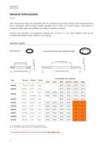
General information Axial incremental rings are compatible with RLS standard LM encoder family or the component-level RoLin readheads, which provide reliable operation due to their non-contact design. Incremental or analogue output types are available according to industry standards. Various inner diameters are supported ranging from 12 mm to 71 mm. Axial magnetic rings can be installed with adhesive tape, fasteners or by gluing. Selection guide Cross-section C Cross-section N and S (with attachment holes) Compatibility with readheads LM10 Ri - Unique reference mark or only incremental...
Open the catalog to page 2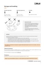
Storage and handling Storage temperature Operating temperature ߌ High resistance to humidity HANDLE WITH CARE! The use of industrial tools during installation or exposure to strong magnets such as a magnetic base is not recommended as it carries the risk of damaging parts of the system which as a result might not perform in accordance with specifications. Use of tools such as drift, punch or similar are expressly forbidden and should not be used during installation to adjust run-out. WARNING! Improper assembly of the readhead and ring may impair function of the magnetic encoder system and...
Open the catalog to page 3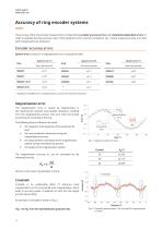
Accuracy of ring encoder systems The accuracy of the ring encoder measurement is influenced by encoder accuracy errors and installation-dependent errors. In order to evaluate the total accuracy, each of the significant errors must be considered. Fig. 1 shows a typical accuracy error plot with marked particular influences. Encoder accuracy errors System error consists of a magnetisation error, crosstalk and SDE. System error [°] * Significant installation error expected due to coarse inner diameter tolerance. Magnetisation error The following factors influence the result: ⦁ the magnetic...
Open the catalog to page 4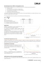
Sub divisional error (SDE) or interpolation error The sub divisional or interpolation error is a periodical accuracy error. It is influenced by the following factors: ⦁ the length of poles, ⦁ the homogeneity and cycle definition of magnetic poles, the quality of the signal processing, the sensing distance (ride height) of the installed readhead, the characteristics of the internal AMR sensor. The SDE leads to speed ripples in applications where the encoder is used as speed feedback, e.g. in speed control loops. For axial rings, SDE is strongly influenced by ride height. The maximum SDE at...
Open the catalog to page 5
Magnetic ring design Structure Magnetic layer and stainless steel carrier OPTIONAL: VHB Double-sided acrylic adhesive tape Appearance and markings The position of the magnetised reference mark is always the same, on the inner side of the ring as shown in the figure below. Incremental track Magnetic field viewer Reference mark The shape of the reference mark may vary. The image is for representation purposes only. Magnetic ring surface markings (printed or engraved) Magnetic ring markings depend on ring size and design. They are either printed on the magnetic layer or engraved on the...
Open the catalog to page 6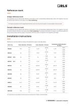
Reference mark Unique reference mark The readhead must be ordered with reference mark option A (see corresponding readhead data sheet). The magnetic ring must be ordered with reference mark option A (see Part numbering). The shape and position of the magnetised reference mark are critical so this option is only available as factory order. Periodic reference mark The readhead must be ordered with reference mark option C (see corresponding readhead data sheet). The magnetic ring must be ordered without reference mark option B (see Part numbering). The position information is output in...
Open the catalog to page 7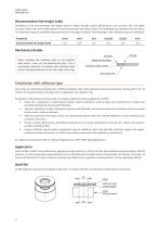
Recommended ride height table Installation at the recommended ride height results in better encoder system performance, such as lower SDE and higher accuracy. Please refer to the table below for the recommended ride height values. The readheads are calibrated at these values. The maximum range of installation tolerances for the ride height is shown in the drawings of the individual rings and readheads. Readhead Recommended ride height [mm] Mechanical details OD step When installing the readhead refer to the stainless steel carrier / hub, not the elasto-ferrite layer. This is particularly...
Open the catalog to page 8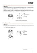
Installation by gluing Application The surfaces to be stuck together must be cleaned very thoroughly before the adhesive is applied. It is worth first using abrasive cloth (abrasive rating 150-200) then degreasing using cellulose moistened with a grease solvent. The adhesive should be applied to the parts to be stuck together as soon as possible after mixing, to ensure the best possible bond. The parts to be assembled usually need to be fixed under pressure. It is not necessary to apply extreme pressure. At temperatures below room temperature, the hardening process takes somewhat longer....
Open the catalog to page 9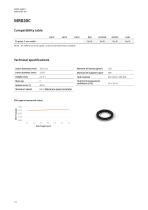
No Ri - No reference mark option, only incremental track available Technical specifications Outer diameter (mm) Material of magnetic layer Hub thermal expansion coefficient (CTE) Maximum speed Go to Maximum speed calculator SDE (typical measured value) SDE [°] (pkpk) SDE [°] (pkpk)
Open the catalog to page 10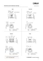
Dimensions and tolerances are in mm. Drawings show the positive direction of rotation of the ring and not the readhead. RLM MR020C + RLC2HD Pripravil: Žiga Bajt Datum: 19.02.2021 Dimensions and installation drawings * For height dimensions see RLC2IC data sheet available at RLS media center.
Open the catalog to page 11All RLS catalogs and technical brochures
-
ArtosTM_DBD01_05
21 Pages
-
Artos_DRD01_03
21 Pages
-
RE58_RE58D04_04
22 Pages
-
RE22_RE22D01_10
9 Pages
-
RM22_RM22D01_05
9 Pages
-
MR_MR02D02_04
41 Pages
-
LM13_LM13D01_13
17 Pages
-
LM10 Series
20 Pages
-
AksIM-2_MBD07_05
14 Pages
-
RE16 / RM16
15 Pages
-
SpinCoTM_SP3D01_07
31 Pages
-
AksIM-2_MBD01_11
53 Pages
-
FlexINTM
2 Pages
-
OnAxis™ Redundant_RDD01_01
14 Pages
-
Orbis™
2 Pages
-
DRD01_03
21 Pages
-
SARD01_02
15 Pages
-
ArtosTM_DBD01_05
21 Pages
-
MS Incremental Magnetic Scales
26 Pages
-
AksIM-4
14 Pages


