

- Products
- Catalogs
- News & Trends
- Exhibitions
LM10 Series

LM10 Series
Catalog excerpts

DATA SHEET LM10D01_17 Issue 17, 20th April 2023 LM10 Incremental Magnetic Encoder UNIQUE REFERENCE MARK The LM10 is a non-contact high-speed magnetic encoder designed for linear or rotary motion sensing in harsh environments. It features a compact readhead that rides at up to 1.0 mm from the self-adhesive magnetic scale or ring. Simple to install, the LM10 features a set-up LED and wide installation tolerances. The encoder comes in digital or analogue output variants and offers a range of customer selectable resolutions from 0.244 μm to 250 μm. WEAR-FREE MEASURING PRINCIPLE Customer selectable resolutions High speed operation Excellent dirt immunity to IP68 Linear or rotary position sensing Unique bidirectional reference mark INDUSTRIAL AUTOMATION ASSEMBLY LINES Non-contact and wear-free measuring principle CE compliant, including RoHS Highly resistant to shock, vibration and pressure LINEAR MOTOR PRINTING TECHNOLOGY
Open the catalog to page 1
General information Engineered for extreme service, the solid-state LM10 linear encoders operate from –10 °C to +80 °C, have water-proof sealing to IP68 and are highly resistant to shock, vibration and pressure. The robust magnetic scale and ring are also resistant to various chemicals commonly found in industry. The non-contact, frictionless design eliminates wear and reduces hysteresis. Choose your LM10 system The robust LM10 readhead is compatible with the RLS MS10 incremental scale as well as the RLS axial and radial rings. You can select the length of the MS scale up to 150 m. There is also...
Open the catalog to page 2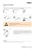
Storage and handling All data given below refer to the readhead only. Complete systems with magnetic scale or ring may have other limitations. For more information, see the MSD01, MR01D01 or MR02D02 data sheet at RLS Media center. Storage temperature Operating temperature Readhead is ESD sensitive - handle with care. Do not touch electronic circuit, wires or sensor area without proper ESD protection or outside of ESD controlled environment. This encoder system is a high performance metrology product and must be handled carefully. The use of industrial tools during installation or exposure to...
Open the catalog to page 3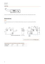
Label on the readhead contains: full PN, 6 digits long serial number and 2D code containing the serial number. Reference sensor position mark Dimensions and tolerances are in mm. Dimensions without tolerance values are in accordance with ISO 2768-m. 3D model available for download at RLS Media center. General tolerances for linear dimensions according to ISO 2768 m Tolerance class
Open the catalog to page 4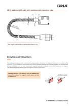
LM10 readhead with cable with stainless-steel protection tube Max. length of cable with flexible stainless-steel conduit is 10 m. Fasteners (not provid Reference mark Installation instructions The readhead LED must be green at all measuring length positions. Otherwise, the installation is not performed correctly. The M3 0.1 mm to 1.0 mm thick plastic spacer (shim) can be used to facilitate installation. For Fasteners optimal installation, the recommended (not provided) thickness of the shim is 0.3 mm. After mounting the magnetic scale, place the plastic shim and the readhead on the magnetic scale....
Open the catalog to page 5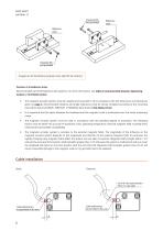
DATA SHEET LM10D01_17 Fasteners M3 (not provided) Reference mark Reference mark Images are for illustration purposes only. Valid for all versions. Position of installation holes Recommended use of M3 fasteners with washers. For more information, see Table of recommended fastener tightening torques at RLS Media center. ⦁ The magnetic encoder system must be installed and mounted in strict compliance with the dimensions and tolerances given on page 4. All permissible distance and angle tolerances must be strictly complied according to the mounting instructions found at MSD01, MR01D01 or MR02D02...
Open the catalog to page 6
Technical specifications System data Pole length Maximum measuring length System accuracy Linear application Different accuracy grades of MS magnetic scale are available. Refer to MSD01 available at RLS Media center. Rotary application Axial: Refer to MR01D01 available at RLS Media center. Radial: Refer to MR02D02 available at RLS Media center. Reference mark Unique / Periodic / DCRM (information about distance coded ref. mark can be found in the MSD01 at RLS Media center). Max. 13 bit (~0.244 µm) For details refer to the Table of available resolutions. Maximum speed Linear application Refer...
Open the catalog to page 7
Cable Type PUR high flexible cable, drag-chain compatible, double-shielded Outer diameter Jacket material White wire Other wires 20 million cycles at 25 mm bend radius 0.08 mm2, 28 AWG, 0.23 Ω/m 20 million cycles at 50 mm bend radius Bend radius (internal radius) Dynamic torsion * Cable is not torsion specified. A continuous torsion of the cable in a dynamic application could result in malfunctioning of the encoder system. ** Applied only for option with additional alarm output (for IA, IC; not available for PRG option). Cable tolerances LM10 with cable LM10 with cable with stainless-steel protection...
Open the catalog to page 8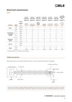
Electrical connections Colour (option Function Power Incremental / analogue signals Reference signals Alarm* * For alarm output “07” option must be ordered. Shield connection Figure below shows a recommended shield termination in order to ensure electromagnetic compatibility. Customer electronics Encoder system Inner shield Power supply Output signals Housing of the encoder is galvanically connected with the housing of the connector via the cable outer shield. The encoder system must be correctly integrated to achieve EMC compliance. In particular, atten
Open the catalog to page 9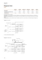
Response time Set-up time Interpolation conversion time Transition time *Shortened reaction time option. Set-up time is the time needed for the encoder readhead to start reading the position information after power-on (see diagram 1). Interpolation conversion time is the time needed for the encoder readhead to convert the position information into an output signal. Transition time is the time it takes the encoder readhead to switch from an alarm state to a valid output signal (see diagram 2). Diagram 1: Set-up time Power supply voltage ABZ High impedance *In alarm state LED flashes red/green....
Open the catalog to page 10All RLS catalogs and technical brochures
 Artos_DRD01_03
21 Pages
 RE58_RE58D04_04
22 Pages
 RE22_RE22D01_10
9 Pages
 RM22_RM22D01_05
9 Pages
 MR_MR01D01_06
55 Pages
 MR_MR02D02_04
41 Pages
 LM13_LM13D01_13
17 Pages
 AksIM-2_MBD07_05
14 Pages
 RE16 / RM16
15 Pages
 SpinCoTM_SP3D01_07
31 Pages
 AksIM-2_MBD01_11
53 Pages
 FlexINTM
2 Pages
 OnAxis™ Redundant_RDD01_01
14 Pages
 Orbis™
2 Pages
 DRD01_03
21 Pages
 SARD01_02
15 Pages
 DBD01_05
21 Pages
 MS Incremental Magnetic Scales
26 Pages
 AksIM-4
14 Pages


- Angular encoder
- Incremental rotary encoder
- Absolute rotary encoder
- Industrial rotary encoder
- Magnetic rotary encoder
- IP67 rotary encoder
- Compact rotary encoder
- Aluminum rotary encoder
- DC rotary encoder
- Stainless steel rotary encoder
- Ultra-rugged rotary encoder
- SSI angular encoder
- Digital rotary encoder
- High-accuracy rotary encoder
- Incremental linear encoder
- 5VDC rotary encoder
- RS-422 rotary encoder
- Miniature rotary encoder