

- Products
- Catalogs
- News & Trends
- Exhibitions
DRD01_03

DRD01_03
Catalog excerpts

DATA SHEET DRD01_03 Issue 03, 21st June 2024 Artos™ Rotary and Linear Absolute Magnetic Encoder System TRUE ABSOLUTE SYSTEM ArtosTM is an absolute magnetic encoder system designed for motion control applications as a feedback element for angle and velocity control loops. A highly reliable measurement principle and processing provide low position latency, high resolution and high angular velocity. The robust design protects the readhead and magnetic ring from liquid ingress and high temperatures, so they remain undamaged even in extremely contaminated and hot environments. COMPACT ROBUST DESIGN HIGH SPEED AND RESOLUTION True absolute system SSI and BiSS communication protocols High accuracy and resolution Suitable for highly dynamic control loops Compatible with solid rings and partial arc scales Robust design and great EMC compatibility Wide installation tolerances MACHINE TOOL ASSEMBLY LINES INDUSTRIAL AUTOMATION
Open the catalog to page 1
General information ArtosTM provides a true-absolute position information immediately after power-on via the selected communication protocol. The encoder system is extremely reliable due to the large installation tolerances (axial/radial/tangential offsets) and the robust IP67 design of the ring and readhead. The measuring principle is based on a magnetic ring/scale magnetised with the incremental and absolute track with a pseudorandom binary sequence (PRBS) read by RLS proprietary sensor technology. Once installed, the encoder system does not need to be calibrated. To ensure the installation...
Open the catalog to page 2
Storage and handling Storage temperature Operating temperature Readhead is ESD sensitive - handle with care. Do not touch electronic circuit, wires or sensor area without proper ESD protection or outside of ESD controlled environment. This encoder system is a high performance measuring instrument and should be handled with the same care as any other precision instrument. The use of industrial tools during installation or contact with strong magnets, such as a magnetic base, is not recommended as there is a risk that parts of the system will be damaged and may not function to specifications as...
Open the catalog to page 3
Dimensions drawing DATA SHEET DRD01_03 Dimensions and installation drawings Dimensions and tolerances are in mm. Dimensions without tolerance values are in accordance with ISO 2768-m. Ø5 2.5 14 M3 THRU Dimensions drawing Dimensionsdrawing drawing Dimensions A (5 : 1) 3D models are available at RLS website. A (5A: (5 1) : 1) Installation surfaces General tolerances for linear dimensions according to ISO 2768-m Tolerance class Further information on compatible rings and scales can be found in SARD01 and ASD01, available at RLS Media center. Installation surfaces Installation Insta
Open the catalog to page 4
Installation instructions Installation instructions with rings or magnetic scale for partial arc applications The readhead can be installed in 3 different ways - from the left, right or top, as shown in the drawings below. Carefully plan the orientation of the readhead and the ring or magnetic scale. The engraving on the ring and the print on the scale can be used to determine the orientation. We recommend the use of M3 fasteners with washers. For more information, please refer to the Table of recommended fastener tightening torques. After mounting the ring or magnetic scale with the readhead,...
Open the catalog to page 5
Technical specifications System specifications Type of absolute measurement Pseudorandom binary sequence (PRBS) absolute code; RLS proprietary sensor technology Reading type <3.5 µm at nominal ride height SAR057 = 25 arcsec SAR081 = 18 arcsec SAR114 = 13 arcsec SAR162 = 9 arcsec SAR229 = 6 arcsec SAR325 = 4 arcsec SAR478 = 3 arcsec Unidirectional repeatability Rings: up to 23 bits binary resolution (depends on the ring size) Magnetic scales: up to ~0.122 μm See Table of available resolutions. Sensor and processing latency Internal loop refresh rate Maximum speed during power up Electrical data...
Open the catalog to page 6
Cable Cable type 8 core, PUR high flexible cable, braided shield, pairs not twisted Outer diameter White and brown wires 0.14 mm2, 26 AWG, 0.14 Ω/m Other wires 0.08 mm2, 28 AWG, 0.23 Ω/m Cable: Dynamic 50 min. mm Bending radius Cable bending radius 20 million cycles (expected value) at 50 mm bend radius Maximum cable length Flexible application Cable: min. Bending radius Cable bending radius Fixed laying application Continuously flexible application Fixed laying Continuously flexible Min. R35 Min. R10 Min. R35 Min. R10 Flexible application The cable requires adequate strain relief to ensure its...
Open the catalog to page 7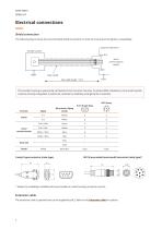
Electrical connections Shield connection The following figure shows the recommended shield termination in order to ensure electromagnetic compatibility. Customer electronics Encoder system 5 to 30 V Serial communication signals GND Outer shield Max cable length = 15 m The encoder housing is galvanically connected to the connector housing. To achieve EMC compliance, the encoder system must be correctly integrated. In particular, attention to shielding arrangements is essential. Serial communication Reserved Shield Wire colour (Flying Leads) DATA+ / SLO+ Bare wire 9-way D-type connector (male type)...
Open the catalog to page 8
Status indicator LED Once the ring or magnetic scale has been installed, the readhead can be easily mounted on the machine using the LED setup indicator. The LED indicator shows the internal status of the encoder and is used to facilitate the installation and diagnosis of the encoder system. According to the table Detailed status description, certain errors are latched, resulting in LED indicating error status persistently. To clear latched error statuses, communication with readhead or readhead power cycle is required. Slow flashing of LED indicates that the encoder is receiving power, but communication...
Open the catalog to page 9
Troubleshooting If the readhead reports an error during operation due to incorrect decoding of the absolute position on the magnetic ring/scale, this indicates a serious problem. Serious problems include incorrect installation or a damaged magnetic pattern on the ring or scale. To determine the cause of the problem, please proceed as follows: ⦁ Make sure that the part number on the readhead and the ring or scale match the required combination. The valid combination of ring and readhead can be verified with the first 6 letters of the part number. Verify that the installation matches the specificaion...
Open the catalog to page 10All RLS catalogs and technical brochures
 Artos_DRD01_03
21 Pages
 RE58_RE58D04_04
22 Pages
 RE22_RE22D01_10
9 Pages
 RM22_RM22D01_05
9 Pages
 MR_MR01D01_06
55 Pages
 MR_MR02D02_04
41 Pages
 LM13_LM13D01_13
17 Pages
 LM10 Series
20 Pages
 AksIM-2_MBD07_05
14 Pages
 RE16 / RM16
15 Pages
 SpinCoTM_SP3D01_07
31 Pages
 AksIM-2_MBD01_11
53 Pages
 FlexINTM
2 Pages
 OnAxis™ Redundant_RDD01_01
14 Pages
 Orbis™
2 Pages
 SARD01_02
15 Pages
 DBD01_05
21 Pages
 MS Incremental Magnetic Scales
26 Pages
 AksIM-4
14 Pages


- Angular encoder
- Incremental encoder
- Incremental rotary encoder
- Absolute rotary encoder
- Industrial rotary encoder
- Magnetic rotary encoder
- IP67 rotary encoder
- Compact rotary encoder
- Aluminum rotary encoder
- DC rotary encoder
- Stainless steel rotary encoder
- Linear encoder
- Ultra-rugged rotary encoder
- SSI angular encoder
- Digital rotary encoder
- High-accuracy rotary encoder
- Incremental linear encoder
- 5VDC rotary encoder
- RS-422 rotary encoder
- Miniature rotary encoder