
Catalog excerpts
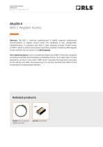
APPLICATION NOTE MCD02_02 Issue 02, 19th September 2023 AksIM-4 BiSS C Register Access Abstract: The BiSS C interface implemented in AksIM supports bidirectional communication in register access mode. The readhead is user configurable. Implementation is compliant with BiSS C (also Standard Encoder Profile known as “BP3”), which is used to group linear and rotary encoders. Details on BiSS register access and BP3 can be found on the BiSS website. User implementation: User can implement bidirectional BiSS in their own hardware according to the BiSS documentation provided by iC-Haus. As an alternative it is also possible to use the iC-Haus chip iC-MB4, which translates the high-level commands on the SPI bus into BiSS. The easiest way is to use the interface E201-9B from RLS including the corresponding software. Related products AksIM-4 off-axis absolute magnetic encoder
Open the catalog to page 1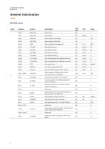
General information BiSS EDS banks Bank Data type Bank address USER start Bank address USER end Min. permited clock periond Min. sampling period adaptive timeout Max. sampling period adaptive timeout Max. Processing time SCD in clocks Max. »power on delay« until control communication is available Number of channels in this device Area of validity for this EDS (number of slave addresses) Memory location for this EDS (slave ID within this device) Bank address for content description of data channel 1 (Profile EDS) Data length for data channel 1 Data format for data channel 1 CRC polynomial...
Open the catalog to page 2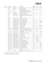
Data type BiSS profile 3 version Length of this profile Profile identification BP3 (content also available in addresses 0x42 and 0x43) Max. “power on delay” until position data is available Encoder type (rotary = 0) Position value (1 position) Data length MULTITURN Data format MULTITURN Data length COARSE Data format COARSE Data length FINE Data format FINE Number of distinguishable revolutions Number of signal periods per revolution Resolution factor per signal period (LSB of interpolation) Absolute accuracy Relative accuracy Angular speed depending accuracy Checksum (sum of all bytes...
Open the catalog to page 3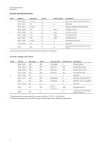
Encoder identification bank Bank Data Type Default value RLS serial number (ASCII characters) RLS part number (ASCII characters) FW version short hash Checksum (sum of all bytes within this bank) * Most values of parameters in identification bank depend on actual part. Encoder configuration bank Bank Data Type Default value Position offset* Position filter value Position filter speed Velocity filter value Multiturn counter preset** Multiturn error arc length** Write protect lock Checksum (sum of all bytes within this bank) * Max allowed value is determined from encoder resolution: SIP_RES –...
Open the catalog to page 4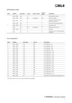
Self-calibration bank Bank Default value Self-calibration status Ring eccentricity shift from rotation axis centre Ring eccentricity angle (phase) Ring radial shift Checksum (sum of all bytes within this bank) Data Type Error map banks* Bank Data Type Checksums of banks 8-23 on addresses
Open the catalog to page 5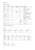
Direct access registers Address Data Type Default value Bank select Profile ID (table B – BP_ID) Serial number (encoded) Command register Encoder detailed status (see chapter »Encoder operating parameters«) Signal level Persistent detailed status Parameter access status register – table D Same as in Identification bank * Parameter value depends on actual part. ** Parameter value changes during operation. Table B Encoder type Table C Encoder size
Open the catalog to page 6
Write access denied Command fetched and executed Write lock active * Bits are one time read - they get cleared on register read, except ‘Write lock active’, which can not be cleared. Bank switching BiSS registers are grouped into the banks in size of 64 bytes. Each register in each bank can be accessed with the address from 0x00 to 0x3F. Before access to a certain bank, it has to be selected in the Bank select register, which is mapped to address 0x40. For further information on bank switching refer to documentation provided by iC-Haus. Read access All registers in AksIM memory are...
Open the catalog to page 7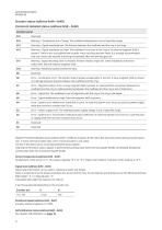
Encoder status (address 0x4A—0x4D) Persistent detailed status (address 0x58 – 0x5B) Detailed status b15 Warning – Temperature out of range. The readhead temperature is out of specified range. Warning – Signal amplitude low. The distance between the readhead and the ring is too large. Warning – Signal amplitude too high. The readhead is too close to the ring or an external magnetic field is present. There is also a possibility that encoder ring is touching encoder head. It is strongly recommended that user checks the encoder mounting immediately after this warning gets set. Warning - Signal...
Open the catalog to page 8
AksIM-4 programming Position offset (encoder zero position), multiturn counter (optional) and register write protection can be programmed to the AksIM readhead. Additional to this, the readhead can be self-calibrated or reset to the factory defaults. Numbers written into registers take effect immediately, with some exceptions - see “value in effect” column in registers description tables. Command execution To execute a command following sequence must be used: ⦁ Write value 0xCD to Key register at address 0x48 ⦁ Write command byte to Command register at address 0x49 Write to key and command...
Open the catalog to page 9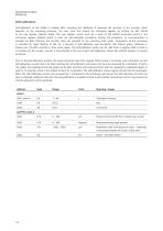
Self-calibration Self-calibration of the AksIM is suitable after mounting the readhead. It improves the accuracy of the encoder, which depends on the mounting precision. The user must first unlock the command register by writing the KEY (0xCD) to the Key register (address 0x48). The next register access must be a write of the SelfCal command (0x41) to the Command register (address 0x49) to start the self-calibration procedure. During the procedure, no communication is possible via BiSS interface; the encoder does not respond to any incoming clock cycles. Completion of the procedure is...
Open the catalog to page 10
Self-calibration status register: Bit Error - Parameters could not be saved to non-volatile memory (system fault). Indication - Error map table is not default (self-calibration was successfully performed). Comparison is executed at power-up and at every command “Save to NVRAM”. Error - Radial displacement is very high. Error - Eccentricity is very high. Error - Numerical error during data processing. Error - Encoder is in error state while calibration is started - aborted. Timeout - Encoder did not complete full revolution (or partial arc) in preset time. Confirmation - Self calibration...
Open the catalog to page 11All RLS catalogs and technical brochures
-
ArtosTM_DBD01_05
21 Pages
-
Artos_DRD01_03
21 Pages
-
RE58_RE58D04_04
22 Pages
-
RE22_RE22D01_10
9 Pages
-
RM22_RM22D01_05
9 Pages
-
MR_MR01D01_06
55 Pages
-
MR_MR02D02_04
41 Pages
-
LM13_LM13D01_13
17 Pages
-
LM10 Series
20 Pages
-
AksIM-2_MBD07_05
14 Pages
-
RE16 / RM16
15 Pages
-
SpinCoTM_SP3D01_07
31 Pages
-
AksIM-2_MBD01_11
53 Pages
-
FlexINTM
2 Pages
-
OnAxis™ Redundant_RDD01_01
14 Pages
-
Orbis™
2 Pages
-
DRD01_03
21 Pages
-
SARD01_02
15 Pages
-
ArtosTM_DBD01_05
21 Pages
-
MS Incremental Magnetic Scales
26 Pages


