AksIM-4™ Off-Axis Rotary Absolute Magnetic Encoders_MCD01_01
1 /24Pages

AksIM-4™ Off-Axis Rotary Absolute Magnetic Encoders_MCD01_01
1 /24Pages
Catalog excerpts

DATA SHEET MCD01_01 Issue 01, 3rd April 2023 AksIM-4™ Off-Axis Rotary Absolute Magnetic Encoders HIGH ACCURACY AksIM-4 is a non-contact, high performance off-axis absolute rotary encoder. It is designed for integration into applications with limited space and for rotary systems with larger shaft diameters or requirements for large opening. A hollow ring, true absolute functionality and high-speed operation make this encoder suitable for many applications. The AksIM-4 encoder system consists of an axially magnetised ring and a readhead. The encoders are equipped with BiSS communication interface and offer binary resolutions up to 21 bits per revolution. LARGE SIZE True absolute system High speed operation Custom magnetic sensor ASIC Self-calibration option High repeatability SERVO MECHANISMS ROBOTIC JOINTS ROTARY TABLES
Open the catalog to page 1
General information Dimensions and tolerances are in mm. Dimensions without tolerance values are in accordance with ISO 2768-m. + The AksIM-4 encoder operates in a temperature range between -40 °C and +105 °C and is highly resistant to shock and vibration. It has a built-in advanced self-monitoring function that continuously checks several internal parameters. Error reports, warnings and other status signals are available on all communication interfaces and visualised with the on-board LED. MRA axial magnetic ring The AksIM-4 encoder system is suitable for use in industry, medicine and logistics....
Open the catalog to page 2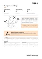
Storage and handling Storage temperature Operating temperature HANDLE WITH CARE. This encoder system is a high performance metrology product and should be treated with the same care as any other precision instrument. Use of heavy duty industrial tools or exposure to strong magnets, such as a magnetic base, is unacceptable and risks of irreparable damage to the product. The magnetic ring should not be exposed to magnetic field densities higher than 50 mT on its surface, as this can damage the ring. Please see Chemical resistance or contact RLS. Readhead is ESD sensitive - handle with care. Do...
Open the catalog to page 3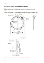
Dimensions and installation drawings Dimensions and tolerances are in mm. Dimensions without tolerance values are in accordance with ISO 2768-m. Encoder assembly MC115DCB20BDNP00 readhead with MRA115 magnetic ring 65° Components area Zero position hole Mounting distance 2.85 ±0.10 Ride height 0.2 ±0.15 DETAIL A Ride height influences noise on the output. See chapter Installation instructions for deta
Open the catalog to page 4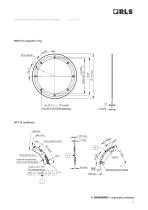
Dimensions and installation drawings External temperature sensor pads 2.2 ±0.1 PTH 4x connecting External temperature Components area sensor connecting pads Components area Zero position mark Zero position mark Mounting surface (gold) Mounting surfac
Open the catalog to page 5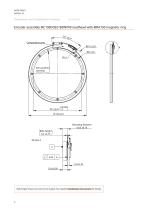
Dimensions and installation drawings Encoder assembly MC150DCB21BDNP00 readhead with MRA150 magnetic ring 50° Zero position slot hole Mounting distance 6.65 ±0.10 Ride height 0.2 ±0.15 DETAIL A A Ride height influences noise on the output. See chapter Installation instructions for details
Open the catalog to page 6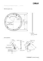
Dimensions and installation drawings Mounting surface Sensor (gold) External temperature sensor connecting pads 4x 2.2 ±0.1 PTH 4x 2.2 ±0.1 PTH 4.2 Metallization 4.2 Metallization Mounting surface (gold)
Open the catalog to page 7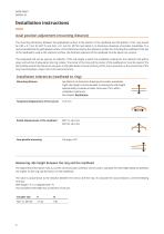
Installation instructions Axial position adjustment (mounting distance) The mounting dimension between the gold-plated surface at the bottom of the readhead and the bottom of the ring should be 2.85 ± 0.1 mm for MC115 and 6.65 ± 0.1 mm for MC150. See detail A on dimension drawings of encoder assemblies. It is recommended that the gold-plated surface on the bottom be used as the reference surface for mounting the readhead. If the top of the readhead is used as the reference surface, the thickness tolerance of the readhead must be taken into account. The integrated LED can be used as an indicator....
Open the catalog to page 8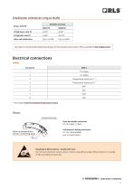
Installation tolerances (ring to shaft) Encoder accuracy After self-calibration R62.5 ±0.1 See table of recommended tightening torques for RLS products (document TTD01) available at RLS media center. R48 ±0.1 Electrical connections * See chapter External isolated temperature sensor Temp. sens. Pin 1 Components area 8-pin low profile connector FCI 10114830-11108LF External temperature sensor connecting pads Pin 1 Counterpart mating connector: FCI 10114826-00008LF and 10114827-002LF Readhead is ESD sensitive - handle with care. Do not touch electronic circuit, wires or sensor area without proper...
Open the catalog to page 9
Technical specifications System data Reading type Axial reading Maximum speed System accuracy Up to ±0.004° / ±15 arcsec after self-calibration Up to ±0.015° / ±54 arcsec without self-calibration For high-accuracy variants contact RLS. Less than unit of resolution Within the range of position noise Encoder speed 12.5 kHz bandwidth, 25 kHz sampling rate, up to 44 kHz refresh rate Electrical data Supply voltage (VDD) Set-up time 100 ms (first data ready after supply voltage is in range), worst case: 200 ms Current consumption Typ. 125 mA, max. 160 mA (without load on the outputs) Output load HBM,...
Open the catalog to page 10
Status indicator LED The LED provides visual feedback on signal strength, error status, and is used for setup and diagnostics. Flashing LED indicates that power is being supplied to the encoder, but communication has not been established. When communication is running at a rate of at least 5 readings per second, LED will be constantly lit. LED signal Status Green Normal operation; position data is valid. Warning; position is valid, but the resolution and/or accuracy might be out of specification. Some operating conditions are outside limits. Error; position data is not valid. Slow flashing Communication...
Open the catalog to page 11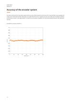
Accuracy of the encoder system Accurate centering of the ring is key to good overall accuracy. Minimising the eccentricity of the ring assembly (using a gauge) and using a drive shaft with precision bearings can usually reduce the error. A typical accuracy chart after good installation (without eccentricity) is shown in the figure below. To improve accuracy after installation, we recommend performing the self-calibration function. Example for encoder size MC115.
Open the catalog to page 12All RLS catalogs and technical brochures
 Artos_DRD01_03
21 Pages
 RE58_RE58D04_04
22 Pages
 RE22_RE22D01_10
9 Pages
 RM22_RM22D01_05
9 Pages
 MR_MR01D01_06
55 Pages
 MR_MR02D02_04
41 Pages
 LM13_LM13D01_13
17 Pages
 LM10 Series
20 Pages
 AksIM-2_MBD07_05
14 Pages
 RE16 / RM16
15 Pages
 SpinCoTM_SP3D01_07
31 Pages
 AksIM-2_MBD01_11
53 Pages
 FlexINTM
2 Pages
 OnAxis™ Redundant_RDD01_01
14 Pages
 Orbis™
2 Pages
 DRD01_03
21 Pages
 SARD01_02
15 Pages
 DBD01_05
21 Pages
 MS Incremental Magnetic Scales
26 Pages
 AksIM-4
14 Pages


- Incremental encoder
- Incremental rotary encoder
- Absolute rotary encoder
- Magnetic rotary encoder
- Industrial rotary encoder
- IP67 rotary encoder
- Compact rotary encoder
- DC rotary encoder
- Aluminum rotary encoder
- Stainless steel rotary encoder
- Linear encoder
- Ultra-rugged rotary encoder
- SSI angular encoder
- Digital rotary encoder
- 5VDC rotary encoder
- Incremental linear encoder
- High-accuracy rotary encoder
- Non-contact rotary encoder
- Miniature rotary encoder