

- Products
- Catalogs
- News & Trends
- Exhibitions
AksIM-2_MBD01_11

AksIM-2_MBD01_11
- True absolute system with a custom magnetic sensor ASIC.
- Resolution up to 20 bits with a multiturn counter option.
- High-speed operation and low profile, non-contact design.
- Integrated status LED and high repeatability.
- Self-calibration option and no hysteresis.
- Operating temperature range: -40 °C to +105 °C.
- Resistant to shock and vibration.
- Communication interfaces: BiSS, UART, SPI, PWM, SSI.
- System accuracy: ±0.004° to ±0.014° after self-calibration.
- Supply voltage: 4.5 V to 5.5 V.
- Magnetic rings should not be exposed to magnetic field densities higher than 50 mT.
- Proper ESD protection is required when handling readheads.
- Installation tolerances are critical for maintaining accuracy, with specific guidelines for axial and radial displacement.
- Mounting can be done using glue, with specific recommendations for glue type and application process.
Catalog excerpts

DATA SHEET MBD01_11 Issue 11, 6th May 2024 AksIM-2 Off-Axis Rotary Absolute Magnetic Encoder HIGH ACCURACY HIGH SPEED AksIM-2 is a non-contact, high performance off-axis absolute rotary encoder designed for integration into applications with limited space. A hollow ring, true absolute functionality and high-speed operation make this encoder suitable for many applications. The AksIM-2 encoder system consists of an axially magnetised ring and a readhead. The encoders are equipped with BiSS, Asynchronous serial (UART), SPI, PWM or SSI communication interfaces and offer a range of binary resolutions up to 20 bits per revolution. MULTITURN COUNTER True absolute system Multiturn counter option Custom magnetic sensor ASIC High speed operation Self-calibration option High repeatability COLLABORATIVE ROBOTS ROBOTIC JOINTS
Open the catalog to page 1
General information The AksIM-2 encoder operates in a temperature range between -40 °C and +105 °C and is highly resistant to shock and vibration. It has a built-in advanced self-monitoring function that continuously checks several internal parameters. Error reports, warnings and other status signals are available on all communication interfaces and visualised with the on-board LED. The AksIM-2 encoder system is suitable for use in industrial and medical applications. A typical application is a robotic arm joint with a cable feed through the ring, or a precision gearbox where the ring is mounted...
Open the catalog to page 2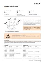
Storage and handling Storage temperature Operating temperature HANDLE WITH CARE. This encoder system is a high performance metrology product and should be treated with the same care as any other precision instrument. Use of heavy duty industrial tools or exposure to strong magnets, such as a magnetic base, is unacceptable and risks of irreparable damage to the product. The magnetic ring should not be exposed to magnetic field densities higher than 50 mT on its surface, as this can damage the ring. Please see Chemical resistance or contact RLS. Readhead is ESD sensitive - handle with care. Do...
Open the catalog to page 3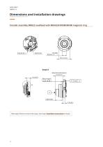
Dimensions and installation drawings Dimensions and tolerances are in mm. MB022 readhead with MRA022HP008DMN00 magnetic ringMRA022HP008DMN00 Encoder assembly MB022 readhead with magnetic ring Detail A Mounting dimension 6.3 ±0.15 6.2 ±0.3 Ride height influences noise on the output. See chapter Installation instructions for details.
Open the catalog to page 4
Dimensions and installation drawings Press-fit mounting to shaft D8: recommended shaft OD tolerance is r6 (+0.019 / +0.028)
Open the catalog to page 5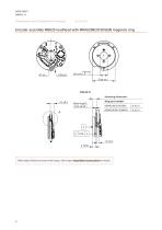
Dimensions and installation drawings Encoder assembly MB029 readhead with MRA029BC010DSE00 magnetic ring 0RXQWLQJGLPHQVLRQ Mounting dimension: 0's Ring part number 'HWDLO$ Ride height influences noise on the output. See chapter Installation instructions for details.
Open the catalog to page 6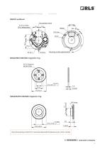
Dimensions and installation drawings s s Press-fit mounting to shaft D12.7: recommended shaft OD tolerance is p7 (+0.018 / +0.036)
Open the catalog to page 7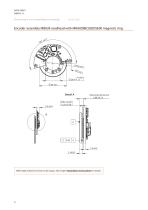
Dimensions and installation drawings Encoder assembly MB039 readhead with MRA039BC020DSE00 magnetic ring Ride height influences noise on the output. See chapter Installation instructions for details.
Open the catalog to page 8
Dimensions and installation drawings MRA039BC020DSE00 magnetic ring [)RUIDVWHQHUV 0,62
Open the catalog to page 9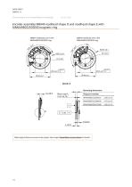
Dimensions and installation drawings Encoder assembly MB049 readhead shape D and readhead shape E with MRA049BC025DSE00 magnetic ring Ring part number Ride height influences noise on the output. See chapter Installation instructions for details.
Open the catalog to page 10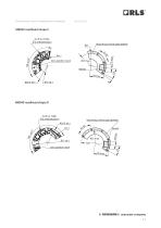
Dimensions and installation drawings
Open the catalog to page 11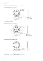
Dimensions and installation drawings * Also possible with suitable M2. Mounting with glue. See chapter installation instructions for more details.
Open the catalog to page 12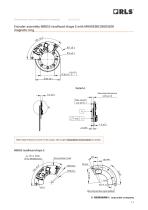
Dimensions and installation drawings 0%UHDGKHDGVL]H( ZLWK05$%&'6(ULQJ 0%UHDGKHDGVL]H( Encoder assembly MB053 ZLWK05$%&'6(ULQJ magnetic ring readhead shape E with MRA053BC030DSE00 r 'HWDLO$ Ride height influences noise on the output. See chapter Installation instructions for details. 'HWDLO$
Open the catalog to page 13
Dimensions and installation drawings * Also possible with suitable M2. Mounting with glue. See chapter Installation instructions for more details.
Open the catalog to page 14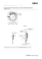
Dimensions and installation drawings Encoder assembly MB064 readhead shape D with MRA064BC040DSE00 magnetic ring 'HWDLO$ Ride height influences noise on the output. See chapter Installation instructions for more details.
Open the catalog to page 15
Dimensions and installation drawings * Also possible with suitable M2.
Open the catalog to page 16
Dimensions and installation drawings Encoder assembly MB080 readhead with MRA080BC055DSE00 magnetic ring Ring part number Ride height influences noise on the output. See chapter Installation instructions for more details.
Open the catalog to page 17
Dimensions and installation drawings * Also possible with suitable M2.
Open the catalog to page 18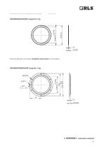
Dimensions and installation drawings Mounting with glue. See chapter installation instructions for more details.
Open the catalog to page 19
Installation instructions Axial position adjustment (ride height) The distance between the sensor and the ring should be between 0.05 mm and 0.35 mm. See detail A on dimension drawings of encoder assemblies. Using the gold-plated surface on the bottom as a reference surface for mounting the readhead is recommended. If the top side of the readhead is used as a reference surface, note that the thickness tolerance of the readhead must be taken into account. Also make sure that the signal traces and components are not in contact with mechanical assembly. Optionally, you may also use shims for height...
Open the catalog to page 20
Installation tolerances (ring to shaft) Ring / shaft fit After self-calibration See table of recommended tightening torques for RLS products available at RLS media center. Mounting rings with glue (option “G” in part number) Rings that can only be mounted with glue: MRA049BG034DSN00, MRA053BG040DSN00 and MRA080BG064DSN00. It is possible to install any type of AksIM-2 ring with glue. However, RLS does not recommend or supply any type of glue. Contact a local company that sells glue for further help in selecting the correct glue type. When choosing the correct type of glue, consider the following...
Open the catalog to page 21
Electrical connections Asynchronous serial Soldering pads * See chapter External isolated temperature sensor 8-pin low profile connector FCI / AMP 10114830-11108LF -horizontal FCI / AMP 10114828-11108LF -vertical (readhead MB022 only) Note: On some connectors there is “Pin 1” marking imprinted, which is sometimes in a wrong position and must be ignored. Counterpart mating connector: FCI / AMP 10114826-00008LF and 10114827-002LF Soldering pads Dimensions: 2.54 x 1.14 mm with 1.875 mm pitch Locking features of the connector: Retention system on the bottom side - bumps on the plug and dimples in...
Open the catalog to page 22All RLS catalogs and technical brochures
 Artos_DRD01_03
21 Pages
 RE58_RE58D04_04
22 Pages
 RE22_RE22D01_10
9 Pages
 RM22_RM22D01_05
9 Pages
 MR_MR01D01_06
55 Pages
 MR_MR02D02_04
41 Pages
 LM13_LM13D01_13
17 Pages
 LM10 Series
20 Pages
 AksIM-2_MBD07_05
14 Pages
 RE16 / RM16
15 Pages
 SpinCoTM_SP3D01_07
31 Pages
 FlexINTM
2 Pages
 OnAxis™ Redundant_RDD01_01
14 Pages
 Orbis™
2 Pages
 DRD01_03
21 Pages
 SARD01_02
15 Pages
 DBD01_05
21 Pages
 MS Incremental Magnetic Scales
26 Pages
 AksIM-4
14 Pages


- Incremental encoder
- Incremental rotary encoder
- Absolute rotary encoder
- Industrial rotary encoder
- Magnetic rotary encoder
- DC rotary encoder
- IP67 rotary encoder
- Compact rotary encoder
- Aluminum rotary encoder
- Stainless steel rotary encoder
- Linear encoder
- Ultra-rugged rotary encoder
- SSI angular encoder
- Digital rotary encoder
- 5VDC rotary encoder
- Incremental linear encoder
- High-accuracy rotary encoder
- RS-422 rotary encoder
- Miniature rotary encoder