

PF900
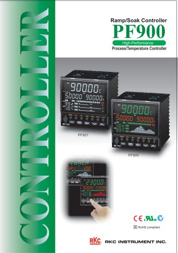
PF900
Catalog excerpts
Ramp/Soak Controller I RESET RUN RX MAN HOLD SWPSET PIN END 1 C € cBIbC in RoHS compliant
Open the catalog to page 1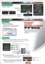
EVOLUTION High intensity white color display High Intensity Display All necessary information is visible on the easy-to-read front display. Program/Segment remaining time display (Unit: hour:min/min:sec) Display with 11-segment characters Output program memory group number set value Wait zone High (group 1) set value Time signal/ Digital output indicators Running pattern/ Segment display Gradient state display Program pattern/ Output p bargraph g p display p y Control Advanced control New control algorithm RSS (Ramp Soak Stabilizer) EVOL LUTION A newly developed control algorithm designed exclusively...
Open the catalog to page 2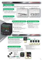
Large memory The PF900 can store up to 1024 segments (99 patterns with 10 segments each to 10 patterns with 99 segments each). (32 patterns by 32 segments, yet all patterns are linkable to form a large program) Time signal output Enhanced flexibility Segment signal output Each segment Two types of signal modes You can select a pattern mode that works within the pattern or a segment mode that works within the segment. (Please specify one of the two) Level-PID or segment PID Select the best PID option for your application. The set values are stored in 8 stage levels or in 8 memory groups. Satisfies...
Open the catalog to page 3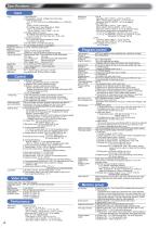
Specifications p Input • Universal input a) Temperature, current, voltage (low) input group Thermocouple input K, J, E, T, R, S, B, N, PLII, W5Re/W26Re, U, L, PR40-20 RTD Pt100, JPt100 (3-wire type) DC Voltage input (input impedance: 1MΩ) 0 to 1V, 0 to 100mV, 0 to 10mV, -100 to +100mV, -10 to +10mV, -1 to +1V b) Voltage (high) input group DC Voltage input (input impedance: 1MΩ) 0 to 5V, 1 to 5V, 0 to 10V, -5 to +5V, -10 to +10V c) Current input group DC Current input (input impedance: 50Ω) 4 to 20mA, 0 to 20mA (Use dip switch to change input group.) Sampling time 0.1 sec (0.05sec/0.25sec is selectable.)...
Open the catalog to page 4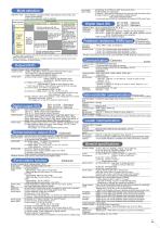
Operation mode Reset (RESET), program (RUN), fixed setpoint control (FIX), and manual control (MAN) Action when operation mode is selected. *1 Program status is retained unless the instrument is reset. If program control is selected, control starts from the retained status. • Output may result in a bump in spite of a bumpless transfer action if the selected control mode is P action, PD action, or ON/OFF action. Output types: Number of event Up to 4 points (event 1 to 4)_ Event types Process, Deviation, Band, SV, MV Event setting range Event output type Additional features for event output: Heater...
Open the catalog to page 5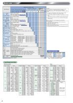
Model code Model and Suffix Code If inter-controller communication (master-slave operation) is used, select code: W, X, or Y (that means "with communication 2") for a master device, and 5 or X (communication 1: RS-485) for a slave *1 For program or retransmission output, specify voltage or current. For digital output, specify relay or open collector output. 2 Heater break alarm (HBA) is not available or current/continuous voltage output. Loop break alarm (LBA) is not available for heat/cool PID control type. resistance) input. Control output (OUT1, OUT2) assignment by control action Control output...
Open the catalog to page 6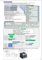
Quick start code 2 • Quick start code 2 tells the factory to ship with each parameter preset to the values detailed as specified by the customer. Quick start code is not necessarily specified when ordering, unless the preset is requested. These parameters are software selectable items and can be re-programmed in the field via the manual. (See Digital Input Allocation table) See Digital output code table ( See Digital output code table ) ( See Digital output code table ) ( See Digital output code table ) ANSI/RKC standard protocol MODBUS protocol Quick start code 2 (Initial setting code) © @ ®...
Open the catalog to page 7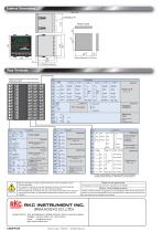
Unit : mm (Terminal cover) Rear Terminals ■ Please use M3 solderless terminal with width smaller than 5.9mm. ■ Unused terminals are not supplied with screws. Code 0 RESET RUN STEP HOLD (32) Ptn.No. Code 1 RESET RUN STEP (32) Ptn. Code 4 RESET RUN STEP HOLD Dir/Rev Code 5 RESET RUN STEP HOLD Ptn. INC Digital inputs • Open collector output • Open collector output (1) Voltage pulse/Voltage Current WAIT release WAIT release WAIT release WAIT release WAIT release WAIT release Digital inputs To use communication 2 (inter-controller communication). please specify RS-232C or RS-485 for communication...
Open the catalog to page 8All RKC INSTRUMENT INC catalogs and technical brochures
 VGR-B100
8 Pages
 DP-350*A / DP-700
4 Pages
 MA901
MA9016 Pages
 MA900
MA9006 Pages
 COM-ME-1
2 Pages
 SRX
SRX8 Pages
 SRZ
SRZ12 Pages
 SB1
SB18 Pages
 REX-F9000
3 Pages
 HA930
HA9306 Pages
 GZ400 / GZ900
12 Pages
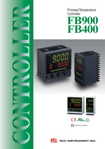 FB400 / FB900
12 Pages
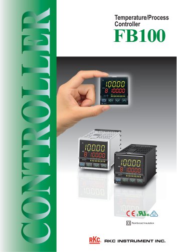 FB100
FB1008 Pages
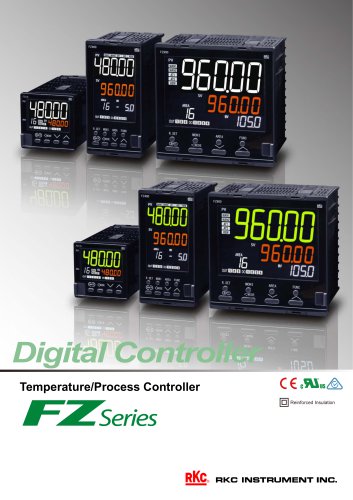 FZ110 / FZ400 / FZ900
12 Pages
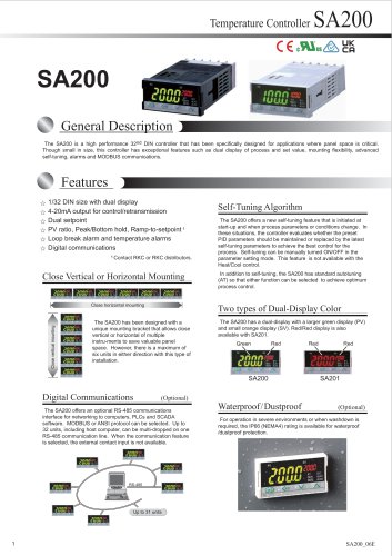 SA200
SA2006 Pages
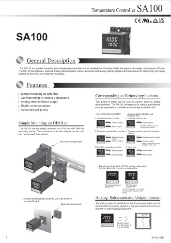 SA100
SA1006 Pages
 RZ SERIES
4 Pages
 SB1 Series
8 Pages
 RB SERIES
8 Pages
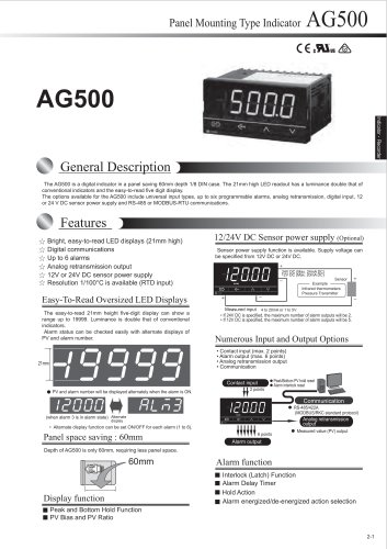 AG500
AG500108 Pages
 PRODUCT CATALOG
167 Pages


- Temperature probe
- Automation software solution
- Level limit switch
- Liquid level detector
- Control software
- Digital temperature control
- Switching relay
- Digital pyrometer
- Digital indicator
- Monitoring software solution
- Pressure probe
- Measurement software
- Programmable logic controller
- Digital temperature controller
- Network software
- Membrane pressure sensor
- Portable pyrometer
- Reporting software