Catalog excerpts

Proceedings of the ASME 2012 11th Biennial Conference On Engineering Systems Design And Analysis ESDA2012 July 2-4, 2012, Nantes, France ESDA2012-82491 AN ELASTIC-PLASTIC ANALYSIS OF PROFILE EVOLUTION IN CYLINDRICAL ROLLER BEARINGS Spiridon S. Creţu* RKB Europe SA Balerna, 6828, Switzerland Email: spiridon.cretu@rkbbearings.com ABSTRACT The roller profile appears to be the key element to attain a longer rating life for both cylindrical and tapered roller bearings. A genuine elastic analysis is able to optimize the roller profile to obtain a stress distribution in the contact zones that provides enhanced operational reliability and greater insensitivity to misalignment. For traditional cylindricalcrowned roller profile design class I discontinuities exist at the intersection points of roller profile with the crowning radius as well as at the end chamfer. In an elastic analysis these discontinuities generate very sharp increases in pressure distribution diminishing the rating life of the bearing. In fact, these local increases in pressure distribution are able to overcome, locally, the yield limit and to induce both plastic deformations and residual stresses. After a certain number of cycles the material will shakedown elastically to a slightly modified roller profile and a stable state of compressive residual stresses. If were taken place, these changes have to be considered in the life evaluation. An analysis model has been developed to simulate the nonlinear strain rate dependent deformation of rolling bearing steel stressed in the elastic-plastic domain. Marcelin I. Benchea Technical University of Iasi Iasi, 700050, Romania Email: marcelin_ben@yahoo.com The model is developed in the frame of the incremental theory of plasticity by using the von Mises yield criterion and PrandtlReuss equations. By considering an isotropic and non-linear kinematic hardening laws the model accounts for the cyclic hardening phenomena. For each new load increment new increments for the components of stress and strain tensors, but also increments of residual stresses, are computed for each point of the 3D mesh. Both the new contact geometry and residual stresses distributions, are further considered as initial values for the next loading cycle, the incremental technique being reiterated. The cyclic evaluation process of both the plastic strains and residual stresses is performed until the material shakedowns. For the case of cylindrical roller bearings with cylindrical-crowned roller profile, the role played by the crowning geometry on pressure distribution is pointed out for both the elastic analysis and elastic-plastic analysis. Further, the modified rating lives are evaluated using the methodology given in ISO 16281-2008. KEYWORDS: elastic-plastic contact, non-linear hardening, plastic deformation, cylindrical roller bearings, reference rating life. __________________ *Address all correspondence to this author 1 Copyright © 2012 by ASME
Open the catalog to page 1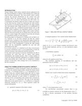
INTRODUCTION Design changes which reduce material stresses appeared to be the main possibilities to improve roller bearing lives within the same envelope dimensions. The cross-section roller’s profile controls the pressure distribution in the contact area and radically affects the bearing dynamic load rating and life, Ioannides et al. [1], Harris and Kotzalas [2], ISO 16281 [3]. Consequently the primary target has been to reduce the stresses in the roller-raceway contact by optimizing the roller profile. The diversity of crowning profiles includes: the single straight line with chamfer...
Open the catalog to page 2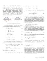
DIGITAL FORMULATION OF ELASTIC CONTACT A uniformly spaced rectangular array is built on the hypothetical rectangular contact area with the grid sides parallel to the x and y-axes. The nodes of the grid are denoted by (i, j), where indices i and j refer to the grid columns and rows, respectively. In the considered Cartesian system, the coordinates of the grid node (i, j) are denoted by (xi, yj ) and are given by xi = i * Δx, (0 ≤ i < Nx) and yj = j * Δy, (0 ≤ j < Ny) where Δx and Δy are the grid spaces in the x and y-directions, respectively. The real pressure distribution is approximated by...
Open the catalog to page 3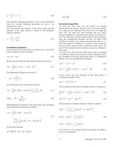
α= C⎛ −γ ε ⎞ ⎜1 − e ⎟ ⎠ γ ⎝ p (20) The kinematic hardening parameters C and γ can be determined when the isotropic hardening parameters Q∞ and b∞ are assigned zero values. The link between the intensity of the stress tensor and the intensity of the strain tensor is assured by the RambergOsgood’s equation: εe = σe ⎛σ ⎞ +⎜ e ⎟ E ⎝ B ⎠ N (21) Constitutive equations The increment of the total strain is assumed to be a sum of the elastic and plastic strain increments: dε = dε e + dε p (22) Hooke’s law provides the differential of elastic strain tensor: [ 1 dε = (1 + ν ) ⋅ dσ ij − ν ⋅ dσ kk ⋅ δ...
Open the catalog to page 4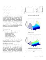
( dσ ( n +1) = dσ ( n +1) + dσ Rn +1) (35) Finally, the stress and strain tensors are: σ ( n +1) = σ ( n ) + dσ ( n +1) εp ( n +1) =εp (n) + dε p ( n +1) (36) (37) a. The evaluation process of plastic strains and residual stresses is performed in all points of the loaded half-space. As long as the load attains its final value, the integration of the plastic strains provides the plastic displacements that modify the contact geometry. Both, the new contact geometry and residual stresses distribution are further considered as initial values for the next loading cycle, the incremental technique...
Open the catalog to page 5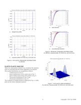
a. b. a. axial direction. circumferential direction. straight line profile. Figure 6. RESIDUAL STRESSES DISTRIBUTIONS, (Fr=450 kN, crowned profile: R1=8100 mm, zk=0.010 mm). b. crowned profile: R1=8100 mm, zk=0.024 mm. Figure 5. 2D ELASTIC PRESSURE DISTRIBUTIONS, FR=450 kN. ELASTIC-PLASTIC ANALYSIS When the elastic-plastic material was considered the plasticity loop was reiterated until the elastic-shakedown was attained. The resulted distributions are exemplified as follows: - residual stresses in Fig. 6; - plastic displacement on the contact area in Fig. 7; - plastic displacements along...
Open the catalog to page 6All RKB Europe catalogs and technical brochures
-
Company Business Card - T3
1 Pages
-
Cylindrical rolelr bearings
2 Pages
-
Technological bearings
2 Pages
-
Project S12
2 Pages
-
RKB Product Table
2 Pages
-
This Is RKB
24 Pages
-
RKB Phosphate Treatment
2 Pages
-
RKB General Information Form
12 Pages
-
Project "241 KPP VL"
2 Pages
-
Project "EPB"
2 Pages
-
Project "MDU"
2 Pages
-
Project "ABI"
2 Pages
-
TQOS Maintenance
3 Pages
-
AF2D Multiroll Cage Design
2 Pages
-
RKB_Europe_SA_ISO_9001
1 Pages
-
RKB_Europe_SA_ISO_14001
1 Pages
-
RKB_Europe_SA_OHSAS_18001
1 Pages
-
RKB_Europe_SA_ISO_27001
1 Pages
-
RKB_Europe_SA_ISO_10002
1 Pages
-
RKB_Europe_SA_ISO-TS_16949
1 Pages
-
RKB General Quality Program
50 Pages
-
RKB Special Projects
68 Pages
-
RKB Metals Industry Leaflet
2 Pages
-
RKB Company Snapshot
2 Pages
-
RKB Brief Company Profile
2 Pages
-
RKB_Taper_Roller_Bearings_Assy
39 Pages
-
RKB Bearings Production Range
34 Pages
-
RKB Bearings Catalogue
168 Pages
-
RKB Taper Roller Bearings Assy
39 Pages
-
Made in RKB
1 Pages
-
RKB Basic Load Ratings
14 Pages
-
Why RKB
1 Pages
-
Bearing Industry Matrix
2 Pages
-
RKB Basic Information Form
1 Pages
-
RKB_Business_Card_T3
1 Pages
-
RKB_Business_Card_T2
1 Pages
-
RKB Message of the President
2 Pages
-
RKB Brief Introduction
2 Pages
-
RKB Digital Presentation
50 Pages
-
RKB PRODUCTION FLOW CHART
1 Pages
-
Company name and motto
6 Pages


