- Catalogs
- RKB Europe
- From 2D-3D CAD to FEM Analysis - The Development of an Application at RKB
From 2D-3D CAD to FEM Analysis - The Development of an Application at RKB
1 /16Pages

From 2D-3D CAD to FEM Analysis - The Development of an Application at RKB
1 /16Pages
Catalog excerpts
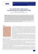
FROM 2D/3D CAD TO FEM ANALYSIS: THE DEVELOPMENT OF AN APPLICATION AT RKB RKB TECHNICAL REVIEW - APRIL 2010 1 From 2D/3D CAD to FEM Analysis: the Development of an Application at RKB Ciprian Radu, Catalin Danaila RKB Bearing Industries - Advanced Software Engineering Unit Abstract: RKB Bearing Industries produces a wide range of bearings of different size, but most of all it is specialized in manufacturing custom-made bearings for special applications. In this paper, the development of an oil platform will be followed to make clear how the transition from handmade 2D paper sketch to CAD design has led to an overall enhancement of the quality, performance, reliability and delivery time of our bearings. We will show how 2D/3D CAD tools and FEM analysis software are used to study the behavior of the bearings required by specific applications, providing customers with the best possible technical solutions. Key words: Bearing, Design, 2D, 3D, CAD, FEM, Oil platform 1. History Since the earliest times, the need to draw a plan or a sketch of the things to be built or manufactured appeared. It is very possible that technical drawings predated even the written language. The drawing board inscripted with a temple plan from the city of Lagash in Babylon is the oldest known technical drawing (3rd millennium B.C.). The ancient Greeks (Euclid, Pythagoras, Thales, Plato, and Aristotle) had a big contribution on how drawings are made today, with their study of geometry. One of the oldest examples from the medieval period is the Plan of Saint Gall (figure 1), which was created somewhere between 819 and 826 A.D. and depicts an entire Benedictine monastic compound, including churches, houses, stables, kitchens, workshops, brewery, infirmary, and even a special house for bloodletting [10]. The contemporary technical drawing has its roots in 15th century, in the Renaissance Era, with artists like the Italian architect Filippo Brunelleschi, who is the first to use mathematical perspective to redefine Gothic and Romanesque space and to establish new rules of proportion and symmetry (figure 2). In the 18th century, the mathematician Gaspard Monge was the first to use descriptive geometry, when he drew up a fortification plan that would prevent enemies from seeing or firing at a military position (figure 3). The isometric drawing was later introduced, in early 19th century, by Englishman William Farish [11] (figure 4). Before the 18th century, there was no need for interchangeable parts, the components were selected randomly, so that they fit together, and there was no accurate drawing for them. All products were made one at a time, which made each one of them unique. Through the 19th century, many of the designs started with a handmade sketch, which was then changed into a wooden model before being constructed [10]. One of the first efforts to create a program, standardize drawings and establish a mechanical drawing school, came from Philadelphia Franklin Institute, in 1824. Architecture was among the first design disciplines that made use of conventions of plan, elevation and section, in design and production. The higher complexity of the architectural projects generated a separation between design and construction. The Industrial Revolution pushed engineers to use architectural conventions [13; 14]. Together with the Industrial Revolution came the mass production of the same part, and designs started to be made with the interchangeable concept in mind. For this to be accomplished, parts needed to be identical, within designed tolerances. Naturally, this is possible only with detailed technical drawings of every part of the assembly to be built. Sometimes the drafting was handmade by the project engineer, but, due to the massive amount of work that was necessary, this job was usually left in the hands of specialized drafters. The drafters used a smooth surface Fig. 1 - The Plan of Saint Gall
Open the catalog to page 1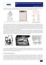
FROM 2D/3D CAD TO FEM ANALYSIS: THE DEVELOPMENT OF AN APPLICATION AT RKB RKB TECHNICAL REVIEW - APRIL 2010 2 with right angle corners and straight sides, onto which they placed a piece of paper. For drawing, they used a Tsquare that was attached on one of the sides of the table and that could slide across the paper [16; 17]. Fig. 2 - Filippo Brunelleschi’s drawing Fig. 3 - Example of descriptive geometry Fig. 4 - Example of geometric perspective drawing views There, parallel lines could be drawn by only using the T-square and a technical pen, but usually the T-square was used to hold other devices...
Open the catalog to page 2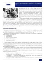
FROM 2D/3D CAD TO FEM ANALYSIS: THE DEVELOPMENT OF AN APPLICATION AT RKB RKB TECHNICAL REVIEW - APRIL 2010 3 Fig. 6 - The Sketchpad system Sketchpad system was able to create images that could be rotated, moved, scaled, stored and modified with the help of a light pen, which is considered to be the predecessor of the mouse (figure 6). This revolutionized the way people could interact with computers. The graphical capabilities of the Sketchpad showed the potential for computerized drawing in design. While he was a professor of electrical engineering at the University of Utah, Sutherland continued...
Open the catalog to page 3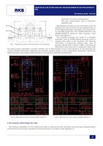
FROM 2D/3D CAD TO FEM ANALYSIS: THE DEVELOPMENT OF AN APPLICATION AT RKB RKB TECHNICAL REVIEW - APRIL 2010 4 Fig. 7 - Application sketch with the position of the bearings - elimination of human drawing errors; - shift from paper-based work to electronic paperless one. RKB Bearing Industries has the full benefit of the 2D drafting and uses AutoCAD for the representation of its 2D bearing drawings, assemblies and components. For the RKB application, the 23248CAW33XS1A and 23048CAW33XS1A spherical roller bearings have been used (figure 7). The assembly drawings are made in a standard template, used...
Open the catalog to page 4
FROM 2D/3D CAD TO FEM ANALYSIS: THE DEVELOPMENT OF AN APPLICATION AT RKB RKB TECHNICAL REVIEW - APRIL 2010 5 The next step in CAD is represented by the 3D modeling of the components, and the simulating operation of the assembly model. There are many 3D CAD software on the market, the most notable being CATIA, Pro/ENGINEER, SolidWorks, Solid Edge and Inventor [9]. While 2D CAD revolutionized the way drawings are made, 3D CAD revolutionized the way products are designed. In the beginning of 3D CAD, in the 1990's, companies purchased software with no clear modeling strategy and without knowing their...
Open the catalog to page 5All RKB Europe catalogs and technical brochures
 Cylindrical rolelr bearings
2 Pages
 Technological bearings
2 Pages
 Project S12
2 Pages
 RKB Product Table
2 Pages
 This Is RKB
24 Pages
 RKB Phosphate Treatment
2 Pages
 RKB General Information Form
12 Pages
 Project "241 KPP VL"
2 Pages
 Project "EPB"
2 Pages
 Project "MDU"
2 Pages
 Project "ABI"
2 Pages
 TQOS Maintenance
3 Pages
 AF2D Multiroll Cage Design
2 Pages
 RKB_Europe_SA_ISO_9001
1 Page
 RKB_Europe_SA_ISO_14001
1 Page
 RKB_Europe_SA_ISO_27001
1 Page
 RKB_Europe_SA_ISO_10002
1 Page
 RKB General Quality Program
50 Pages
 RKB Special Projects
68 Pages
 RKB Metals Industry Leaflet
2 Pages
 RKB Company Snapshot
2 Pages
 RKB Brief Company Profile
2 Pages
 RKB_Taper_Roller_Bearings_Assy
39 Pages
 RKB Bearings Production Range
34 Pages
 RKB Bearings Catalogue
168 Pages
 Made in RKB
1 Page
 RKB Taper Roller Bearings Assy
39 Pages
 Why RKB
1 Page
 RKB Basic Load Ratings
14 Pages
 Bearing Industry Matrix
2 Pages
 RKB_Business_Card_T3
1 Page
 RKB_Business_Card_T2
1 Page
 RKB Message of the President
2 Pages
 RKB Brief Introduction
2 Pages
 RKB Digital Presentation
50 Pages
 Company name and motto
6 Pages


- Steel bearing
- Ball bearing
- Radial bearing
- Single-row bearing
- Precision bearing
- Axial bearing
- Double-row bearing
- High-speed bearing
- Deep groove ball bearing
- Cylindrical roller bearing
- Bearing with cage
- Angular-contact bearing
- Tapered roller bearing
- Sealed bearing
- Bearing for heavy-duty applications
- High-precision bearing
- Axial deep groove ball bearing
- Combined bearing