- Catalogs
- RK Rose+Krieger GmbH
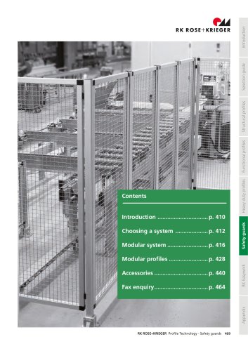
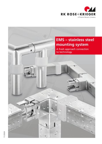
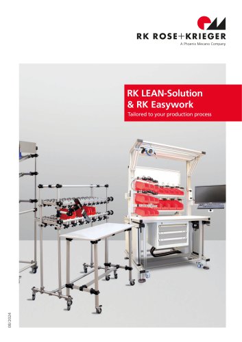
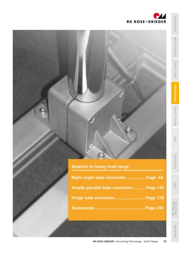
- Heavy duty linear units D-Line
- Company
- Products
- Catalogs
- News & Trends
- Exhibitions
Heavy duty linear units D-Line
1 /50Pages

Heavy duty linear units D-Line
1 /50Pages
Catalog excerpts
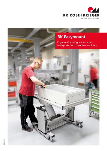
A Phoenix Mecano Company
Open the catalog to page 1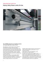
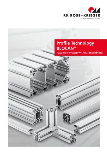
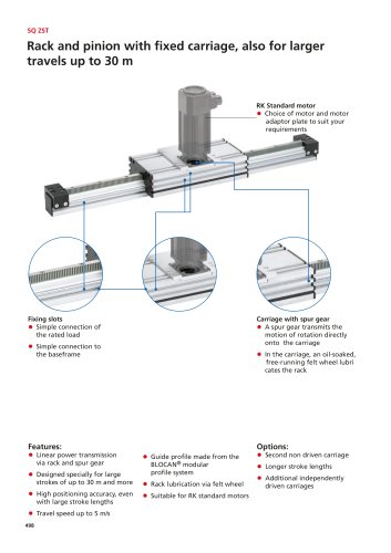
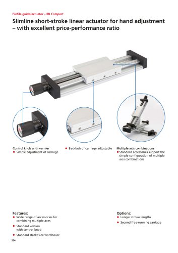
Heavy duty linear units D-Line Heavy duty linear units D-Line The STRONG dimension in handling systems for heavy loads has a name: D-Line This whole new range of linear units is based on BLOCAN® heavy-duty profiles (D-profiles). D-Line puts into practice all the advantages of the latest developments in aluminium-alloy technology. This ensures a low specific weight, thus keeping the drive unit as small as possible – which is of great benefit when using axis that operate in sequence. Increased dynamic performance for the efficient use of short cycle times. FEM calculation helps to create highly-efficient...
Open the catalog to page 2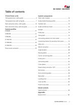
Table of contents D-Line linear units System components System profiles
Open the catalog to page 3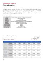
Heavy duty linear units D-Line The guide body of the linear unit consist of extruded aluminium profiles from the familiar BLOCAN®- system range of D-profiles. These are supplied in standard lengths of 6 m. See the max. travel data in the ordering tables. It is technically possible two join two profiles to each other at the ends to obtain a greater stroke length (of up to 14 m). You should however consult with our Technical Department before doing so. Optional fixing holes can be made in the guide tables to customer specifications on request. Technical description
Open the catalog to page 4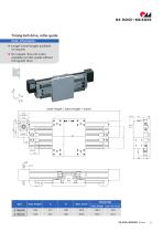
Order information: • Longer travel lengths available on request • On request, this unit is also available as roller guide without timing belt drive
Open the catalog to page 5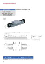
Order information: Timing-belt drive, ball rail guide • Longer travel lengths available on request • On request, this unit is also available as roller guide without timing belt drive
Open the catalog to page 6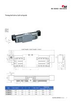
total length = basic length + travel {**]—rr
Open the catalog to page 7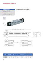
Order information: Timing-belt drive, ball rail guide • Longer travel lengths available on request • On request, this unit is also available as roller guide without timing belt drive
Open the catalog to page 8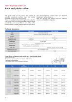
Heavy duty linear units D-Line The guide body of the linear unit consist of extruded aluminium profiles from the familiar BLOCAN®- system range of D-profiles. These are supplied in standard lengths of 6 m. See the max. travel data in the ordering tables. It is technically possible two join two profiles to each other at the ends to obtain a greater travel length (of up to 50 m). You should however consult with our Technical Department before doing so. Rack and pinions with angled teeth are used on versions with ballball rail guides. Technical description
Open the catalog to page 10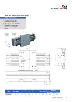
Order information: • Longer travel lengths available on request • On request, this unit is also available as roller guide without rack and pinion drive
Open the catalog to page 11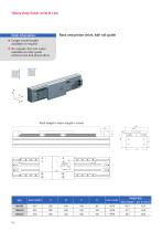
Order information: Rack and pinion drive, ball rail guide • Longer travel lengths available on request • On request, this unit is also available as roller guide without rack and pinion drive
Open the catalog to page 12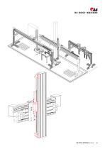
fUiRK ROSE+KRIEGER RK ROSE+KRIEGER D-Line 13
Open the catalog to page 13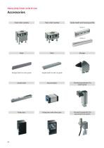
Heavy duty linear units D-Line Track roller module
Open the catalog to page 14
fiiRK ROSE+KRIEGER RK ROSE+KRIEGER D-Line 15
Open the catalog to page 15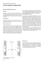
Heavy duty linear units D-Line D-Line system components Brakes / Holding of linear axes Holding This means, when the machines is switched off, e.g. the Z-axis is moved to its initial position and then it is secured against falling down. In this way, it will be possible to replace for instance the motor or the gear unit easily. Slowing down That means, if the power or control unit fail or an emergency switch off is caused, the axis will be slowed down during its travel. Holding of linear axes Typical machine with linear axes are gantries, linear robots, machining centres and integrated production...
Open the catalog to page 16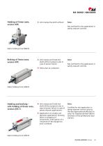
Holding of linear axes, version KPE • Unit clamps the shaft without Note: Not certified for the application in safety-relevant controls. Static holding force 5000 N Braking of linear axes, version KPC • Unit clamps and holds the shaft without pressure also in case of power failure Note: Not certified for the application in safety-relevant controls. Static holding force 3200 N Holding and braking – safe holding of linear axes, version KEC-S • Unit clamps and holds the • Application of a brake unit Certified for the application in safety-relevant control units by the Berufgenossenschaftlichen Institut...
Open the catalog to page 17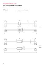
Heavy duty linear units D-Line D-Line system components Safety unit Diagram without fixtures for the slide guide
Open the catalog to page 18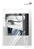
fiiRK ROSE+KRIEGER RK ROSE+KRIEGER D-Line 19
Open the catalog to page 19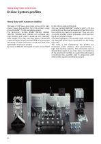
Heavy duty linear units D-Line D-Line System profiles Heavy duty with maximum stability The basis of the heavy duty linear units are the wellknown heavy duty profiles from the product range group BLOCAN® - Profile assembling system. The aluminium profiles 80x80, 80x160, 80x240, 160x160, 160x240 and 160x320 mm combine very high bending and torsion resistance with relatively little weight. This way, even big gantry cranes and machine support structures that used to be mounted exclusively on steel structures, can be now built with lightweight aluminium profiles. By means of DIN slot stones add-on...
Open the catalog to page 20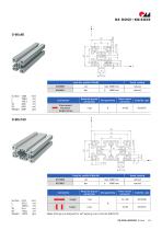
Note: Drillings are designed for self-tapping screw channels (M8 / M12)
Open the catalog to page 21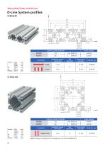
Heavy duty linear units D-Line Note: Drillings are designed for self-tapping screw channels (M8 / M12) Press mount connector
Open the catalog to page 22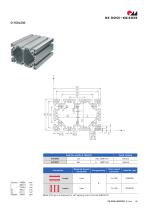
fUiRK ROSE+KRIEGER Code No. profile D-160x240 Note: Drillings are designed for self-tapping screw channels (M8 / M12)
Open the catalog to page 23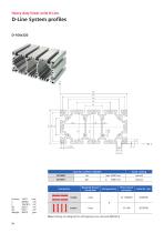
Heavy duty linear units D-Line Note: Drillings are designed for self-tapping screw channels (M8 / M12)
Open the catalog to page 24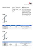
Press mount connector simple, cost-effective and high profile connection no profile machining necessary can be disconnected at any time and reused minimal effort required in construction Material: Galvanised steel The Order No. includes one press mount connector. Depending on the orientation of the connection (longitudinal or transverse), the appropriate number of press mount connectors must be ordered. Please note the information and the connection pictograms in the profile data on page 21 - 24
Open the catalog to page 25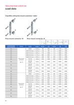
Heavy duty linear units D-Line Press mount connector -N- Press mount connector -R-
Open the catalog to page 26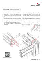
Assembly steps (press mount connector -N-) 1. Screw set screw M10 (2) into thrust compression piece -N- (1) 4. Remove the thrust compression pieces (5) and push them into the slot(s) of the profile to be fixed* 2. Place the thrust compression piece -N- (1) into the profile for the connection strip (3) as an assembly aid 5. Insert the profile with the connection strips (6) into the profile with the thrust compression pieces (7) 3. Align the connection strip (3) and fix it in the screw channel with M8 socket head cap screws (4). It is recommended to create the thread with a thread forming tap....
Open the catalog to page 27All RK Rose+Krieger GmbH catalogs and technical brochures
 RK Eco profiles
16 Pages
 Functional/special profiles
201 Pages
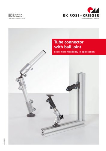 Tube connectors with ball joint
12 Pages
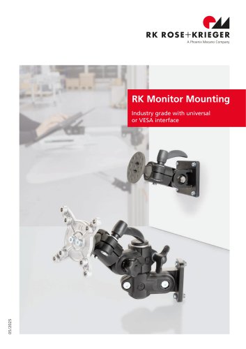 RK monitor mounting
36 Pages
 Linear unit E-II-stainless
24 Pages
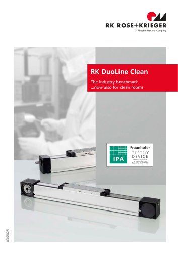 Linear unit RK DuoLine Clean
24 Pages
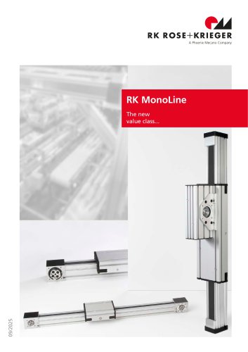 Linear unit RK MonoLine
40 Pages
 BLOCAN® Cable Channel System
12 Pages
 Electric cylinder SLZ 63
32 Pages
 RK DuoLine linear units
44 Pages
 Automated Format Adjustment
12 Pages
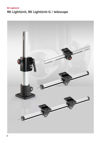 RK LightUnit
28 Pages
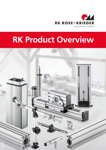 RK Product overview
52 Pages
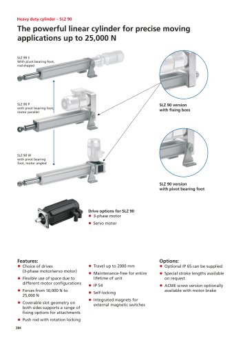 Heavy duty cylinder – SLZ 90
14 Pages
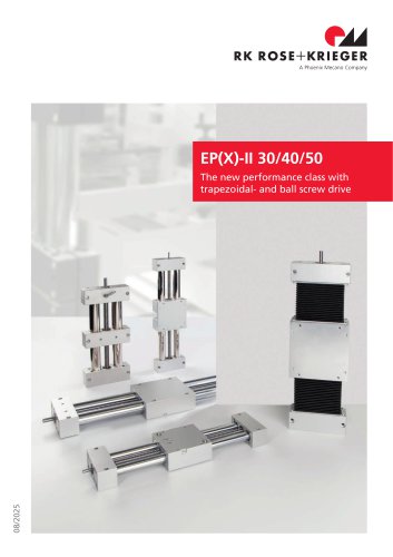 Unités linéaires EP(X)-II (KG)
52 Pages
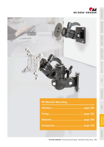 RK monitor mounting
35 Pages
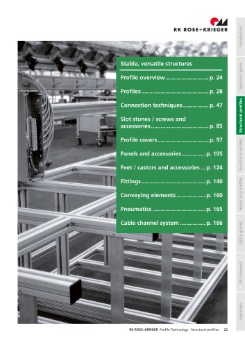 BLOCAN® Structural profiles
151 Pages
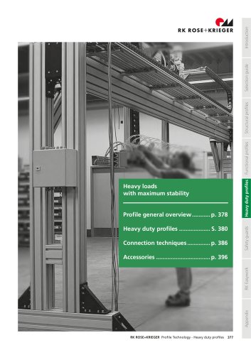 BLOCAN® Heavy duty profiles
31 Pages
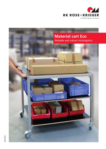 Material cart Eco
4 Pages
 RK stand system
8 Pages


- Electromotor
- DC electromotor
- Rototherm cylinder
- Synchronous motor
- Rototherm actuator
- Rototherm linear actuator
- Rototherm electric actuator
- Rototherm positioning stage
- Translation stage
- Hinge
- Indoor shutter
- Rototherm metal profile
- Metal door
- Metal hinge
- Industrial door
- Compact actuator
- Screw actuator
- Rototherm tube connector
- Rototherm industrial profile