LAFF series
1 /2Pages

LAFF series
1 /2Pages
Catalog excerpts

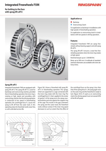
Bonded Disc Pack Flange Chucks LAFF Features • For clamping diameters from 7 mm to 80 mm • High true running accuracy ≤ 0,01 mm • Permissible component tolerance up to IT11 • Short or long clamping length possible • Pull-back against shoulder ring • For thin-walled or solid components • Impervious to ingress of foreign objects due to the rubberized slots in the Bonded Disc Pack Cap bush Seating body The Bonded Disc Pack Flange Chuck consists of a seating body, a cap bush, draw and cross bolts, base and shoulder rings, a Bonded Disc Pack, a thrust ring and a draw bush. The Bonded Disc Pack Flange Chuck is attached to the machine with the seating body. The Clamping Fixture is actuated via the draw bolt, which is connected to the machine power actuating unit. Depending on the required transmitted torque, Bonded Disc Packs of different widths may be installed. The required installation situations for the base and shoulder rings are shown in Fig. 9-2. Cross bolt Draw bolt Base ring Shoulder ring Bonded Disc Pack Thrust ring Draw bush Intermediate Flanges and Spring Force Actuators are shown starting on page 58. 8-2 Clamping principle The Bonded Disc Pack sits pre-loaded in the seating diameter of the seating body. To actuate clamping, the Bonded Disc Pack is raised to an upright position by axial actuating force. The component is centred, pressed flush against the shoulder ring and aligned. The tipping movement of the Bonded Disc Pack converts the axial actuating force into a radial clamping force that is up to ten times higher. Key: Axial actuating force Radial clamping force Axial pull-back
Open the catalog to page 1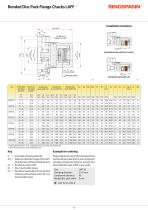
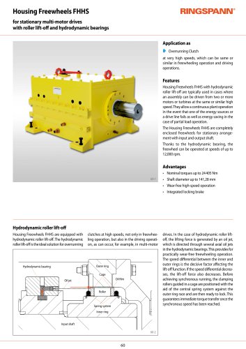
Bonded Disc Pack Flange Chucks LAFF Installation situations Bonded disc pack widths Lb1 and Lb2 Lb3 Bonded disc pack width Lb3 Backstop surface LAFF 22 LAFF 32 LAFF 42 LAFF 52 LAFF 62 LAFF 80 LAFF 90 LAFF 100 Achievable clamping diameter Maximum diameter change** Bonded disc pack width Lb2 Bonded disc pack width Lb3 * Clamping diameter from > up to ≤ adjustable to two places after the decimal point ** of the clamping diameter of the Clamping Element. D = Achievable clamping diameter Δ D = Maximum diameter change of the clamping diameter of the Clamping Element Lb = Bonded disc pack width M =...
Open the catalog to page 2All RINGSPANN catalogs and technical brochures
 Freewheels_2025-2026
124 Pages
 Industrial Brakes_2025-2026
220 Pages
 Shaft-Hub-Connections 2024/2025
100 Pages
 Overload Clutches 2023/2024
80 Pages
 Precision Couplings 2026/2027
60 Pages
 Shaft Couplings 2026/2027
80 Pages
 Beam Couplings
26 Pages
 RCS® Remote Control Systems
64 Pages
 Company brochure
7 Pages
 Your benefit in Harbour Cranes
15 Pages
 RINGSPANN in Energy Plants
7 Pages
 RINGSPANN in Machine tools
7 Pages
 MV 033 FEM
8 Pages
 DH 035 FPM / FPA
2 Pages
 DV 020 FHM
1 Page
 DH 020 FHM
1 Page
 DV 030 FHM
1 Page
 DH 030 FHM
1 Page
 DV 030 FHA
1 Page
 DH 030 FHA
1 Page
 DV 035 FHM / FHA
1 Page
 DH 035 FHM / FHA
1 Page
 DU 060 FHM
2 Pages
 DH 020 FKM
1 Page
 DH 005 PFK
1 Page
 DV 020 FKM
1 Page
 DH 010 PFK
1 Page
 DH 015 PFK
1 Page
 DH 020 PFK
1 Page
 DV 030 PFM
2 Pages
 DH 030 PFM
2 Pages
 DV 035 PFM
2 Pages
 DH 035 PFM
2 Pages
 DU 060 PFM
2 Pages
 DH 010 MSM
1 Page
 DV 020 MSM
1 Page
 DH 020 MSM
1 Page
 DV 020 MKM
1 Page
 DH 020 MKM
1 Page
 HW 075 FHM
2 Pages
 HS 075 HFK
2 Pages
 DV 020 FEM
1 Page
 HW 040 HFA
1 Page
 DV 020 PFK
1 Page
 BCS 600
4 Pages
 DS
DS2 Pages
 DU 060 FPM
2 Pages
 HW 075 HFK
2 Pages
 HS 120 HFK
2 Pages
 KE … FPK series
2 Pages
 RLK 603 S
4 Pages
 RLK 603 K
3 Pages
 RLK 608 series
3 Pages
 RLK 606 series
3 Pages
 RLK 110 series
2 Pages
 RLK 110 K series
2 Pages
 RLK 130 series
2 Pages
 RLK 131 series
2 Pages
 RLK 132 series
2 Pages
 RLK 133 series
2 Pages
 RLK 200 series
2 Pages
 RLK 250 series
2 Pages
 RLK 603 series
4 Pages
 HW 100 HFA
2 Pages
 KE … FHK series
2 Pages
 HI 150 HUK, HI 180 HUK
2 Pages
 FN series
2 Pages
 HW 150 HFA / HW 180 HFA
2 Pages
 DT
DT2 Pages
 HW 063 HFA
1 Page
 RLK 250 L series
2 Pages
 RLK 350 series
2 Pages
 RLK 402 series
2 Pages
 RLK 404 series
2 Pages
 FD series
2 Pages
 RLK 300 series
4 Pages
 Trantorque Mini
2 Pages
 Trantorque OE
2 Pages
 SIKUMAT® SC
6 Pages
 SIKUMAT® SG
6 Pages
 SIKUMAT® ST
6 Pages
 SIKUMAT® SN
6 Pages
 SIKUMAT® SA
6 Pages
 SIKUMAT® SU
6 Pages
 SIKUMAT® SR
6 Pages
 SIKUMAT® SB
6 Pages
 SIKUMAT® SL
6 Pages
 RIMOSTAT® RS
4 Pages
 RSHD series
2 Pages
 RT
RT2 Pages
 PA series
4 Pages
 RFK … TBO series
2 Pages
 RWK … EEO series
2 Pages
 RDA … ESO Series
2 Pages
 RDZ … DTO Series
2 Pages
 RDZ … DFO Series
2 Pages
 RDZ … EEO Series
4 Pages
 RDL … DSO Series
2 Pages
 RDL … DSZ Series
2 Pages
 RDL … DSA Series
2 Pages
 REB … DCO Series
4 Pages
 REK … DQO Series
6 Pages
 REK … DGO Series
4 Pages
 REK … DHO Series
4 Pages
 REK … DGZ Series
4 Pages
 REK … DCO Series
8 Pages
 HDDS series
2 Pages
 REK … ECO Series
2 Pages
 BKFF series
2 Pages
 HKFF series
2 Pages
 KFFF series
2 Pages
 LBDF series
2 Pages
 BKDF series
2 Pages
 HKDF series
2 Pages
 KFDF series
2 Pages
 BKDI series
2 Pages
 SKDZ series
2 Pages
 Pull Only Cables
8 Pages
 FZ … series
6 Pages
 DV 035 FPM / FPA
2 Pages
 DH 030 FPA
2 Pages
 DV 030 FPA
2 Pages
 DH 030 FPM
2 Pages
 DV 030 FPM
2 Pages
 DH 020 FPM
1 Page
 DV 020 FPM
1 Page
 DH 010 FPM
1 Page
 DH 012 FEM
1 Page
 IR series
2 Pages
 SF … P series
2 Pages
 SF series
2 Pages
 FNR series
2 Pages
 FSN series
2 Pages
 FRHN
FRHN2 Pages
 FDN series
2 Pages
 FCN … R series
2 Pages
 FXN series
4 Pages
 FON series
2 Pages
 FGR … R series
2 Pages
 FH series
4 Pages
 FRHD series
2 Pages
 FBL series
2 Pages
 FBE series
2 Pages
 FAV series
2 Pages
 FA series
2 Pages
 FGR … R A2A3 series
2 Pages
 FGR … R A3A4 series
2 Pages
 BC series
2 Pages
 BA series
2 Pages
 FGRN R A5A6 series
2 Pages
 BM series
2 Pages
 FGR R A2A7 series
2 Pages
 FGR R A1A2 series
2 Pages
 FBF series
2 Pages
 FR series
2 Pages
 FB series
2 Pages
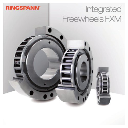
 Integrated Freewheels FXRW
3 Pages


Archived catalogs
 Energy Generation
7 Pages
 Shaft Couplings 2018/2019
76 Pages
 2020 Machine Tools
7 Pages
 Shaft Couplings
76 Pages
 Mining 07/2020
9 Pages
 Precision Clamping Fixtures
100 Pages
 Industrial brake
184 Pages
 Freewheels_2020-2021
112 Pages
 Freewheels_2019-2020
112 Pages
 Overload Clutches
80 Pages
 Industrial Brakes
184 Pages


- Storage cabinet
- RINGSPANN flexible coupling
- RINGSPANN shaft coupling
- RINGSPANN friction brake
- Clamping device
- RINGSPANN flange coupling
- Pack unit
- Single pedal pedal
- Torque coupling
- RINGSPANN rigid coupling
- Transmission coupling
- RINGSPANN disc brake
- RINGSPANN spring brake
- RINGSPANN zero-backlash coupling
- Electric hydraulic power unit
- RINGSPANN friction brake caliper
- RINGSPANN electromagnetic brake
- Friction clutch