Catalogue Cone Clamping Elements for Bending Moments
1 /16Pages

Catalogue Cone Clamping Elements for Bending Moments
1 /16Pages
Catalog excerpts

Cone Clamping Elements for Bending Moments Version 202 2026 6/202 /2027 7 RINGSPANN® Registered Trademark of RINGSPANN GmbH, Bad Homburg
Open the catalog to page 1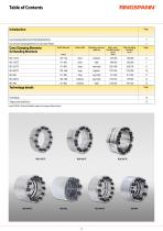
RINGSRANIM* Introduction Issue 03/2026 • Technical details subject to change without notice.
Open the catalog to page 2
Introduction Cone Clamping Elements for Bending Moments RINGSPANN Cone Clamping Elements Cone Clamping Elements for Bending Moments RINGSPANN Cone Clamping Elements are multi-part, ring-shaped Shaft-Hub-Connections. In the drive systems of machines and plants, they transmit torques between shafts and hubs without backlash, safely and permanently. Our series of Cone Clamping Elements for Bending Moments are self-centring, maintenance-free and also suitable for reversing drive systems. They have been specifically developed for applications in which, in addition to high axial and radial loads, additional...
Open the catalog to page 3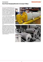
Introduction Use of Cone Clamping Elements in Conveyor Pulleys The use of Cone Clamping Elements in conveyor pulleys is one of the most technically demanding applications of Shaft-Hub-Connections. The Cone Clamping Elements mounted between the pulley shaft and the pulley end disks are exposed to exceptionally high loads here. In addition to simultaneous axial and transverse forces, considerable bending moments occur during operation, which must be absorbed safely and permanently. In order to reliably withstand these complex stresses, our series of Cone Clamping Elements for bending moments have...
Open the catalog to page 4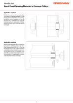
Introduction Use of Cone Clamping Elements in Conveyor Pulleys Application example Backlash free attachment of a conveyor pulley to the shaft of a conveyor belt with an Cone Clamping Element RLK 404. The Cone Clamping Element centres the pulley drum on the drive shaft. As no axial shift occurs during the clamping process, the axial position of the pulley drum in relation to the drive shaft remains unchanged. Application example Backlash free attachment of a conveyor pulley to the drive shaft of a conveyor belt with a Cone Clamping Element RLK 402 TC. The Cone Clamping Element can be used to transmit...
Open the catalog to page 5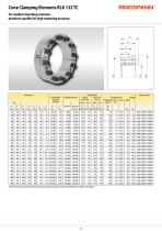
Cone Clamping Elements RLK 133 TC for medium bending moments premium quality for high centering accuracy Bending moments
Open the catalog to page 6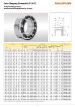
The technical data provided are based on theoretical calculations and the specified screw tightening torques.
Open the catalog to page 7
The technical data provided are based on theoretical calculations and the specified screw tightening torques.
Open the catalog to page 8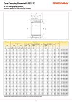
The technical data provided are based on theoretical calculations and the specified screw tightening torques.
Open the catalog to page 9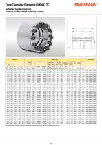
The technical data provided are based on theoretical calculations and the specified screw tightening torques.
Open the catalog to page 10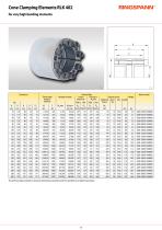
Cone Clamping Elements RLK 402for very high bending moments Si The technical data provided are based on theoretical calculations and the specified screw tightening torques.
Open the catalog to page 11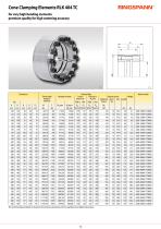
The technical data provided are based on theoretical calculations and the specified screw tightening torques.
Open the catalog to page 12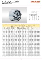
The technical data provided are based on theoretical calculations and the specified screw tightening torques.
Open the catalog to page 13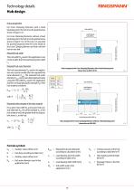
Technology details Hub design Hub arrangement For Cone Clamping Elements with a fixed backstop point, the hub must be positioned as shown in figure 14-1. Hub width NA Load-bearing hub width L1 Required hub width The hub width NA used in the application must not be smaller than the load-bearing hub width L1. Required hub outer diameter Hub arrangement for Cone Clamping Elements with a fixed backstop point (shown here as RLK 136 TC) The hub outer diameter KA used in the application must not be smaller than the required hub outer diameter Kmin. The required hub outer diameter Kmin can be calculated...
Open the catalog to page 14
Technology details The tightening torque Ms listed in the tables must be achieved during assembly and must not be exceeded by more than 10%. If the indicated tightening torque Ms is not achieved, the transmissible torque or axial force, as well as the contact pressures at the shaft and at the hub will be proportionally reduced compared to the values listed in the tables for M or F as well as for Pw and Pn. When the indicated tightening torque Ms is undercut by more than 30%, please contact us. The transmissible torques M which are shown in the tables apply for axial forces F = 0 kN and conversely,...
Open the catalog to page 15
RINGS* mo*W<rf'°"
Open the catalog to page 16All RINGSPANN catalogs and technical brochures
 Freewheels_2025-2026
124 Pages
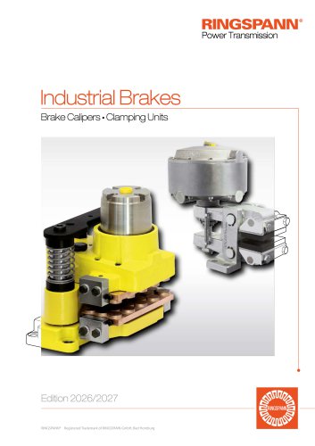 Industrial Brakes_2025-2026
220 Pages
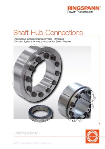 Shaft-Hub-Connections 2024/2025
100 Pages
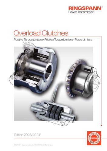 Overload Clutches 2023/2024
80 Pages
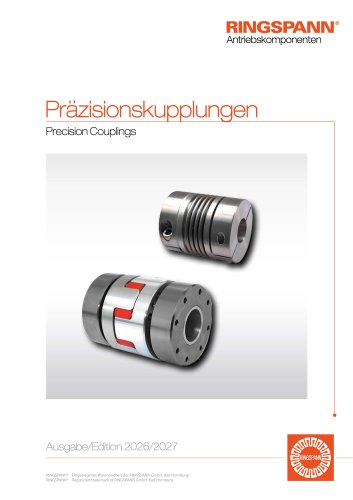 Precision Couplings 2026/2027
60 Pages
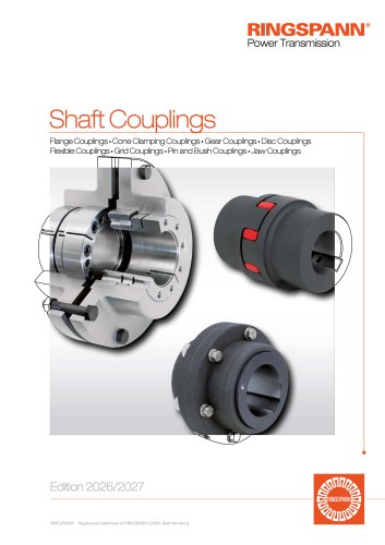 Shaft Couplings 2026/2027
80 Pages
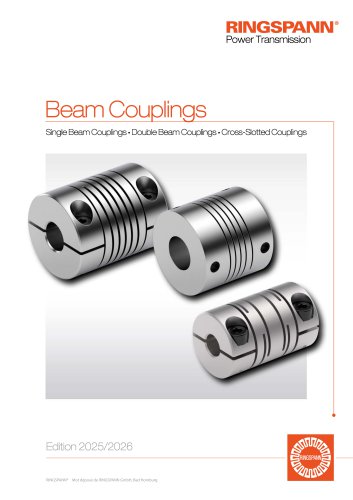 Beam Couplings
26 Pages
 RCS® Remote Control Systems
64 Pages
 Company brochure
7 Pages
 Your benefit in Harbour Cranes
15 Pages
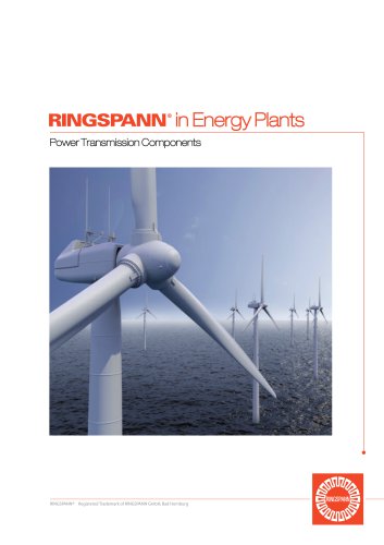 RINGSPANN in Energy Plants
7 Pages
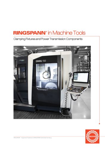 RINGSPANN in Machine tools
7 Pages
 MV 033 FEM
8 Pages
 DH 035 FPM / FPA
2 Pages
 DV 020 FHM
1 Page
 DH 020 FHM
1 Page
 DV 030 FHM
1 Page
 DH 030 FHM
1 Page
 DV 030 FHA
1 Page
 DH 030 FHA
1 Page
 DV 035 FHM / FHA
1 Page
 DH 035 FHM / FHA
1 Page
 DU 060 FHM
2 Pages
 DH 020 FKM
1 Page
 DH 005 PFK
1 Page
 DV 020 FKM
1 Page
 DH 010 PFK
1 Page
 DH 015 PFK
1 Page
 DH 020 PFK
1 Page
 DV 030 PFM
2 Pages
 DH 030 PFM
2 Pages
 DV 035 PFM
2 Pages
 DH 035 PFM
2 Pages
 DU 060 PFM
2 Pages
 DH 010 MSM
1 Page
 DV 020 MSM
1 Page
 DH 020 MSM
1 Page
 DV 020 MKM
1 Page
 DH 020 MKM
1 Page
 HW 075 FHM
2 Pages
 HS 075 HFK
2 Pages
 DV 020 FEM
1 Page
 HW 040 HFA
1 Page
 DV 020 PFK
1 Page
 BCS 600
4 Pages
 DS
DS2 Pages
 DU 060 FPM
2 Pages
 HW 075 HFK
2 Pages
 HS 120 HFK
2 Pages
 KE … FPK series
2 Pages
 RLK 603 S
4 Pages
 RLK 603 K
3 Pages
 RLK 608 series
3 Pages
 RLK 606 series
3 Pages
 RLK 110 series
2 Pages
 RLK 110 K series
2 Pages
 RLK 130 series
2 Pages
 RLK 131 series
2 Pages
 RLK 132 series
2 Pages
 RLK 133 series
2 Pages
 RLK 200 series
2 Pages
 RLK 250 series
2 Pages
 RLK 603 series
4 Pages
 HW 100 HFA
2 Pages
 KE … FHK series
2 Pages
 HI 150 HUK, HI 180 HUK
2 Pages
 FN series
2 Pages
 HW 150 HFA / HW 180 HFA
2 Pages
 DT
DT2 Pages
 HW 063 HFA
1 Page
 RLK 250 L series
2 Pages
 RLK 350 series
2 Pages
 RLK 402 series
2 Pages
 RLK 404 series
2 Pages
 FD series
2 Pages
 RLK 300 series
4 Pages
 Trantorque Mini
2 Pages
 Trantorque OE
2 Pages
 SIKUMAT® SC
6 Pages
 SIKUMAT® SG
6 Pages
 SIKUMAT® ST
6 Pages
 SIKUMAT® SN
6 Pages
 SIKUMAT® SA
6 Pages
 SIKUMAT® SU
6 Pages
 SIKUMAT® SR
6 Pages
 SIKUMAT® SB
6 Pages
 SIKUMAT® SL
6 Pages
 RIMOSTAT® RS
4 Pages
 RSHD series
2 Pages
 RT
RT2 Pages
 PA series
4 Pages
 RFK … TBO series
2 Pages
 RWK … EEO series
2 Pages
 RDA … ESO Series
2 Pages
 RDZ … DTO Series
2 Pages
 RDZ … DFO Series
2 Pages
 RDZ … EEO Series
4 Pages
 RDL … DSO Series
2 Pages
 RDL … DSZ Series
2 Pages
 RDL … DSA Series
2 Pages
 REB … DCO Series
4 Pages
 REK … DQO Series
6 Pages
 REK … DGO Series
4 Pages
 REK … DHO Series
4 Pages
 REK … DGZ Series
4 Pages
 REK … DCO Series
8 Pages
 HDDS series
2 Pages
 REK … ECO Series
2 Pages
 LAFF series
2 Pages
 BKFF series
2 Pages
 HKFF series
2 Pages
 KFFF series
2 Pages
 LBDF series
2 Pages
 BKDF series
2 Pages
 HKDF series
2 Pages
 KFDF series
2 Pages
 BKDI series
2 Pages
 SKDZ series
2 Pages
 Pull Only Cables
8 Pages
 FZ … series
6 Pages
 DV 035 FPM / FPA
2 Pages
 DH 030 FPA
2 Pages
 DV 030 FPA
2 Pages
 DH 030 FPM
2 Pages
 DV 030 FPM
2 Pages
 DH 020 FPM
1 Page
 DV 020 FPM
1 Page
 DH 010 FPM
1 Page
 DH 012 FEM
1 Page
 IR series
2 Pages
 SF … P series
2 Pages
 SF series
2 Pages
 FNR series
2 Pages
 FSN series
2 Pages
 FRHN
FRHN2 Pages
 FDN series
2 Pages
 FCN … R series
2 Pages
 FXN series
4 Pages
 FON series
2 Pages
 FGR … R series
2 Pages
 FH series
4 Pages
 FRHD series
2 Pages
 FBL series
2 Pages
 FBE series
2 Pages
 FAV series
2 Pages
 FA series
2 Pages
 FGR … R A2A3 series
2 Pages
 FGR … R A3A4 series
2 Pages
 BC series
2 Pages
 BA series
2 Pages
 FGRN R A5A6 series
2 Pages
 BM series
2 Pages
 FGR R A2A7 series
2 Pages
 FGR R A1A2 series
2 Pages
 FBF series
2 Pages
 FR series
2 Pages
 FB series
2 Pages
 Integrated Freewheels FXRW
3 Pages


Archived catalogs
 Energy Generation
7 Pages
 Shaft Couplings 2018/2019
76 Pages
 2020 Machine Tools
7 Pages
 Shaft Couplings
76 Pages
 Mining 07/2020
9 Pages
 Precision Clamping Fixtures
100 Pages
 Industrial brake
184 Pages
 Freewheels_2020-2021
112 Pages
 Freewheels_2019-2020
112 Pages
 Overload Clutches
80 Pages
 Industrial Brakes
184 Pages


- RINGSPANN chuck
- Storage cabinet
- RINGSPANN flexible coupling
- RINGSPANN shaft coupling
- RINGSPANN friction brake
- Clamping device
- RINGSPANN flange coupling
- Pack unit
- Single pedal pedal
- Torque coupling
- RINGSPANN rigid coupling
- Transmission coupling
- RINGSPANN disc brake
- RINGSPANN spring brake
- RINGSPANN zero-backlash coupling
- Electric hydraulic power unit
- RINGSPANN friction brake caliper
- RINGSPANN electromagnetic brake
- Friction clutch