
Catalog excerpts

Torsional Highflex Couplings Product Paper & Tech Paper
Open the catalog to page 1
Welcome Machine Building
Open the catalog to page 2
Your system supplier for every aspect of power transmission We say what we mean and mean what we say. We see things from our customers‘ perspective. We are considerate of our employees and their families as well as of our environment and society. RINGFEDER POWER TRANSMISSION is the global market leader in the niche markets of drive technology and is well regarded for its customer-specific, application-oriented solutions that ensure excellent and failure-free operation for its clients. We offer locking devices, damping technology and couplings for OEMs but also for the final customer under...
Open the catalog to page 3
orldwid ite we foryou. Ae -s nytim e, a One are ther n O Al nlin wa ys e ca lculati program find on the r ight solu tion.
Open the catalog to page 4
Your projects are our drive Know-how: Over 90 years of expertise. Rely on decades of engineering expertise from the inventor of the friction spring. As an expert in drive and damping technology, we are your reliable partner wherever forces are at work. Be it the permanent transfer of very high torques due to non-positive or positive connections or the absorption and trapping of extreme energies to protect expensive constructions. Your expert partner: From development to the finished product. We accompany you through to the successful completion of your project. Beginning with the...
Open the catalog to page 5
RINGFEDER® Torsional Highflex Couplings Introduction RINGFEDER® TNR, the novel non-switchable coupling with adjustable dynamic parameters and unchanging outer dimensions. The torsionally flexible coupling can move in all directions, adjusting for angular, axial and radial shaft misalignment between coupled machines. Function principle Adjustable rigidity Using combustion engines such as diesel and gas engines, but also other machines and plant generating undesirable torsional vibrations, the drive train is subject to dynamic excitations. Unavoidable resonances will occur should engine-side...
Open the catalog to page 6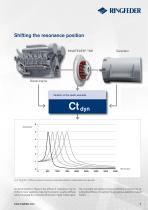
Shifting the resonance position RINGFEDER® TNR Diesel engine Variation of the elastic elements Fig. 2: Interaction of stiffness changes and resonance speeds demonstrated on a diesel engine driven generator As demonstrated in Figure 2, the effects of resonances may be shifted to lower speeds by reducing the dynamic coupling stiffness without changing the connected dimensions. Hyper-critical opera- tion is possible and optimal running smoothness is achieved by adjusting the stiffness of coupling through judicious selection of elastic buffers.
Open the catalog to page 7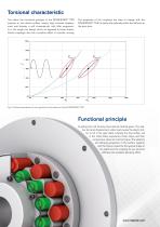
Torsional characteristic The stress the functional principle of the RINGFEDER® TNR imposes on the elastic buffers causes high torsional displacement and thereby a soft characteristic with little progressivity in the single row design which, as opposed to linear characteristic couplings, also has a positive effect on smooth running. The properties of the couplings are easy to change with the RINGFEDER® TNR, to easily and optimally match the stiffness to the drive train. Fig. 3: Torsional characteristic for the single (Cdyn1) and double-row (Cdyn2) RINGFEDER® TNR Functional principle Coupling...
Open the catalog to page 8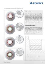
Fig. 4: Functional principle of the RINGFEDER® TNR.1 and the RINGFEDER® TNR.2 Buffer materials Synthetic rubbers and a variety of polyurethanes of different hardness are used for the elastic TNR coupling buffers. The product range is supplemented by special materials for low and high temperatures to render reliable solutions under extreme environmental conditions. The catalogue includes data for standard combinations of the specific materials and customised solutions may be found on demand, with little effort required. The shore hardness of each elastomeric material is the indication of its...
Open the catalog to page 9
Torque characteristics at operating point on outputside Constant, uniform, without torque variation Torque characteristics Minimum load factor SL Uniform with little variations, slight shocks Non-uniform, also API-671, API-610, moderate shocks Drive side Minimum load factor SA E-Motor, turbine Hydraulic motor Combustion machine 1 to 3 cylinders, U-degree > 1:100 Combustion machine 4 and more cylinders, U-degrees ≤ 1:100 Non-uniform, fluctuant, heavy shocks SA = Load factor of drive side: We recommend for drivers with combustion machines to examine by a ‘DSR‘ - torsional vibration...
Open the catalog to page 10
Dimensioning of coupling The dimensioning of the elastic RINGFEDER® couplings is based on the nominal torque TN and maximum impact torque Tmax of the machines. Equation 1) = Nominal torque of machine [Nm] The following equation applies when subjected to the nominal torque: Equation 2) TKN = Nominal torque of coupling = Nominal torque of machine = Load factor of drive side = Load factor of output side Verifying the maximum torque of the coupling: The following equation applies for transient impact torques, which occur e.g. by starting an electric motor: Equation 3) TKmax = Maximum torque of...
Open the catalog to page 11
Dimensioning example Example for dimensioning a coupling for a pump drive with electric motor type IEC 355; preselected type: RINGFEDER® TNR (Single-row). Coupling size TNR 320.1 with buffer quality Vk90 and 8500 Nm nominal coupling torque are selected from the Tech Paper data sheet. The dimension of coupling TNR 320.1 is OK for the performance data. The operating speed of 1480 rpm results in a circumferential speed of 24,8 m/s. Therefore it is recommended to balance the coupling parts. If the shaft-hub connections are dimensioned sufficiently, this coupling can be used. Load factor Drive...
Open the catalog to page 12
Technical installation instructions Arrangement of the coupling parts Observe restoring forces The coupling hubs have to be arranged on the shaft ends in accordance with the coupling type. In order to obtain a shaft-hub connection that is capable of carrying the load it is important to ensure that the hubs are pushed onto the shaft until the face of the hub is flush with the shaft end. The coupling compensates the permissible misalignments with low restoring forces. Please observe the alignment values specified in the assembly and operation manual. If highly loaded bearings are involved,...
Open the catalog to page 13All RINGFEDER POWER TRANSMISSION GMBH catalogs and technical brochures
-
Locking Assemblies
2 Pages
-
RINGFEDER® Product Guide
12 Pages
-
Save your constructions!
8 Pages


