
Catalog excerpts

Damping Technology Friction Springs Industrial buffer Product Paper & Tech Paper Mars Rover Courtesy NASA/JPL-Caltech
Open the catalog to page 1
Welcome Machine Building
Open the catalog to page 2
Your system supplier for every aspect of power transmission We say what we mean and mean what we say. We see things from our customers‘ perspective. We are considerate of our employees and their families as well as of our environment and society. RINGFEDER POWER TRANSMISSION is the global market leader in the niche markets of drive technology and is well regarded for its customer-specific, application-oriented solutions that ensure excellent and failure-free operation for its clients. We offer locking devices, damping technology and couplings for OEMs but also for the final customer under...
Open the catalog to page 3
orldwid ite we foryou. Ae -s nytim e, a One are ther n O Al nlin wa ys e ca lculati program find on the r ight solu tion.
Open the catalog to page 4
Your projects are our drive Know-how: Over 90 years of expertise. Rely on decades of engineering expertise from the inventor of the friction spring. As an expert in drive and damping technology, we are your reliable partner wherever forces are at work. Be it the permanent transfer of very high torques due to non-positive or positive connections or the absorption and trapping of extreme energies to protect expensive constructions. Your expert partner: From development to the finished product. We accompany you through to the successful completion of your project. Beginning with the...
Open the catalog to page 5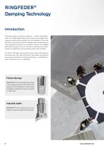
RINGFEDER® Damping Technology Introduction Protecting people, conserving machines – modern dampingproducts are indispensable safety parts inside all technologies when sudden occurring kinetic energy has to be absorbed. In the crash absorption, with machine tools or production plants, impact damping units dissipate the energy of an unwanted collision into targeted deformation energy and can so save lives or prevent precious technology from destruction and respectively extend their durability. For almost 100 years we are experts, when moved masses have to be slowed down fast, safe and...
Open the catalog to page 6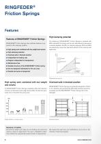
RINGFEDER® Friction Springs RINGFEDER® Friction Springs have multitude features in opposite to other damping systems: • High spring work combined with low weight and volume • High damping potential • Overload-safe in blocked position • Independent of loading rate • Diagram independent of temperature • Maintenance-free • Variable structure of the RINGFEDER friction spring • Can be designed individually for the use case • Parallel and series arrangement High damping potential The damping of RINGFEDER® Friction Springs is standard with 66% wherewith the energy will be soon absorbed and...
Open the catalog to page 8
RINGFEDER® Friction Spring design Independent of loading rate The force-stroke diagram of the RINGFEDER® Friction Spring applies for all operating conditions. In contrast to other damping systems, RINGFEDER® Friction Springs provide full spring work and damping effects even, when the load is applied extremely slowly or quickly. A RINGFEDER® friction spring comprising e elements generally concludes with semi-rings. Its unclamped length L0 is then (the values he, se, We that are necessary for the calculation can be found in the table on p. 12): The total spring stroke can be calculated...
Open the catalog to page 9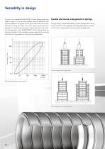
Versatility in design As well as the standard RINGFEDER® Friction Spring range (see table on page 12) we can offer special solutions based on your specific application. The graph (to the right) shows the ratio of outer diameter to spring end force, this can be used to quickly see if an application is possible even though a standard spring is not available. The geometry of the RINGFEDER® Friction Spring allows an optimum utilisation of the available mounting space due to a nested construction, using parallel or series spring arrangements. Parallel and series arrangement of springs The...
Open the catalog to page 10
In aerospace industry the use of RINGFEDER® Friction Springs is perfect. They are used, for example, in the landing flaps or also in the emergency exit doors. The low weight, compact construction and the capability of withstanding temperature variations are required for such applications.
Open the catalog to page 11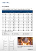
Design notes Force-stroke diagram During the operation of the friction spring two thirds of the input energy is dissipated as frictional heat. The recoil force FR at any point on the diagram is approximately equal to one third of the relative compressive force F. The capacity of the spring is represented by the total area shown below the load curve. The total energy absorption can be calculated by We multiplied by the number of elements. * For type 1316 a separate stroke limitation has to be provided Explanations to table F = Spring stroke for one element D1, d1 = Outer and inner diameter =...
Open the catalog to page 12
Recommendations for the selection and fitting of RINGFEDER® Friction Springs Force Spring work Dimensions RINGFEDER® Friction Springs Force-stroke diagram for one element RINGFEDER® Friction Springs have to be pretensioned with min. of 5%, preferably 10% of the total spring stroke. In order not to impair the lubricant film, the pretensioning force should not exceed 50%. Exceptions are possible after consultation ONLY the special greases recommended by RINGFEDER® must be used for lubrication purposes, this is because the cone surfaces are under a high contact pressure. Generally, the grease...
Open the catalog to page 13
RINGFEDER® Industrial buffer RINGFEDER® Friction Springs can be supplied as complete industrial buffers. A range of buffer types are shown in the table at page 15. Customer-specific buffer versions are possible, e.g.: Variations in flange and/or tappet Water cooling Traction devices and units that work in both traction and compression directions are also possible. Cross section of industrial buffer Overload clutch Traction-compression device Damping diagram Damping work W = 17 Joule Damping Push Force-stroke diagram from an traction-compression device
Open the catalog to page 14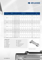
Explanations to table Fv = Preload force = Distance between flange bore db = Diameter of through holes DC = Case diameter Buffer for gas tank (see page17)
Open the catalog to page 15All RINGFEDER POWER TRANSMISSION GMBH catalogs and technical brochures
-
Locking Assemblies
2 Pages
-
RINGFEDER® Product Guide
12 Pages
-
Save your constructions!
8 Pages


