- Catalogs
- RIGCHINA GROUP COMPANY
- Oil and Water Retort Kit
- Products
- Catalogs
- News & Trends
- Exhibitions
Oil and Water Retort Kit
1 /19Pages

Oil and Water Retort Kit
1 /19Pages
Catalog excerpts
50 ML Oil and Water Retort Instruction Manual
Open the catalog to page 1
TABLE OF CONTENTS SECTION
Open the catalog to page 2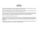
SECTION 1 DESCRIPTION The 210463 and 210465 Model Oil and Water retorts provide a simple, easy, accurate, and direct reading method of determining the percentages of water, oil, and solids which make up drilling fluids. These Oil and Water retorts can also be used to determine the amount of water or solids in oil samples, the water and oil saturation in core samples, or the amount of oil in possibly polluted sea water. The retorts are electrically heated and thermostatically controlled to shut off when a predetermined temperature (930°F ±70°) (498°C ±21°) as specified by API has been reached....
Open the catalog to page 3
SECTION 2 SAFETY CONSIDERATIONS Safe operation of the Model 210463 and 210465 Oil and Water Retorts requires that the operator be familiar with the proper operation and potential hazards associated with this equipment. Retorting the sample poses the potential hazards of the exposed retort stem and Condenser getting hot enough to cause burns and serious injury. Burns can result from touching the hot metal parts of the case near the retort chamber during normal operation. The operator should be aware of these hot areas and avoid contact with them. These Retorts are electrically heated, and as with...
Open the catalog to page 4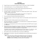
SECTION 3 OPERATING PROCEDURE A. Prepare the retort for service by performing steps A through D under Section 4, CARE OF EQUIPMENT. Lift retort assembly, (parts 1, 2, 4, 5), out of heating compartment. (Refer to Fig. 1.) Unscrew the sample chamber from the Upper Chamber using the square bar Retort Wrench (7). Pack the upper chamber (4) with steel wool (3). Refer to Fig. 1. Fill sample chamber (1) with sample and replace lid (2), allowing excess sample to escape. Wipe excess sample from outside of chamber and lid. NOTE: This is a point where error is often introduced. Be sure that no air is trapped...
Open the catalog to page 5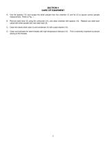
SECTION 4 CARE OF EQUIPMENT A. Use the spatula (13) and scrape the dried sample from the chamber (1) and lid (2) to assure correct sample measurement. Refer to Fig. 1. B. Remove steel wool (3) using the corkscrew (15), and clean chamber with spatula (13). Replace any steel wool caked with dried sample with new steel wool (3). C. Clean the retorts drain tube (4) and condenser (5) with a pipe cleaner (10). D. Clean and lubricate the retort threads with high temperature lubricant (12). This is extremely important to prevent seizing of the threads.
Open the catalog to page 7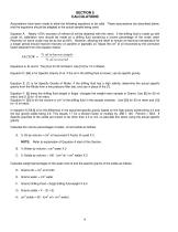
SECTION 5 CALCULATIONS Assumptions have been made to allow the following equations to be valid. These assumptions are described below, and the equations should be adapted to the actual sample being used. Equation A. Nearly 100% recovery of refined oil will be obtained with this retort. If the drilling fluid is made up with crude oil, calibration runs should be made on a drilling fluid containing a known percentage of the crude used. Recovery on some crude may be as low as 60%. However, allowing the retort to remain at maximum temperature for 3 a longer period should improve recovery on paraffin...
Open the catalog to page 8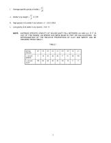
Average specific gravity of solids = K. High gravity (4.3) solids % by volume = (I - 2.6) X 58.8 L. Low gravity (2.6) solids % by volume = 100 - K NOTE: AVERAGE SPECIFIC GRAVITY OF SOLIDS MUST FALL BETWEEN 2.6 AND 4.3. IF IT IS OUT OF THIS RANGE, AN ERROR HAS BEEN MADE IN TEST OR CALCULATIONS. AN APPROXIMATION OF THE RELATIVE PROPORTION OF CLAY AND BARITE CAN BE OBTAINED FROM TABLE 1. TABLE 1 SP.GR SOLIDS
Open the catalog to page 9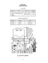
TYPE & SIZE SNAP PLUG
Open the catalog to page 10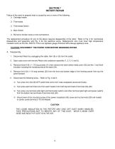
SECTION 7 RETORT REPAIR Failure of the retort to properly heat is caused by one or more of the following: Cartridge heater Thermostat Thermostat Switch Main Switch Burned or broken wires or wire connections The replacement procedure for any of the above requires disassembly of the retort. Refer to Fig. 2 for mechanical disassembly and assembly and Fig. 3 for the electrical wiring. Replacement wire must have high temperature insulation such as Part No. 205772. This is an eighteen gauge American Wire Gauge appliance wire. CAUTION: DISCONNECT THE POWER CORD BEFORE BEGINNING REPAIR. A. Disassembly...
Open the catalog to page 11
6. Remove two sheet metal screws holding the two top pieces of insulation (26) together, and remove the top piece over the heater block. 7. Remove the heater wires from the groove in the insulator, and straighten them, then remove the second piece of insulation. 8. If the heaters are to be replaced and are not stuck in the adapter block, they can be removed and replaced without further disassembly. If they are stuck the adapter block will have to be removed. Refer to Section 7D1c. 9. Carefully remove the loose insulation from around retort adapter. Do not try to reuse this insulation if it is...
Open the catalog to page 12
Fig. 3 – RETORT WIRING, 115 VOLTS AND 230 VOLTS
Open the catalog to page 13
7. Make sure all wiring connections are tight and all crimp connections are properly made using recommended crimping pliers as follows: Refer to Fig. 3. Ground wire from Heater Adapter block mounting screw to receptacle mount screw in receptacle. Terminal Strip (20) Wire of each heater to left top Second wire of each heater to right top Wire from Thermostat switch and wire from pilot light to left bottom Wire from power switch (16) and wire from pilot light to right bottom Wire from thermostat to power Switch (16) 8 Install the following: Panel/Top Assembly, 5 screws (22). Lid assembly, 3 screws...
Open the catalog to page 14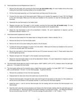
E. Thermostat Removal and Replacement (Item 31) 1. Remove the fish paper (33) covering the thermostat (on old models only). On new models remove the screw holding the thermostat mounting bracket to the insulation block. 2. Pull the thermostat assembly out of the heater block and disconnect the two wires. 3. Connect the two wires to the thermostat switch. Make sure to transfer the capacitor (if used, 230 Volt Model) to the new thermostat. Make sure the wires are installed on the common (C) and the normally open (NO) terminals. 4. Assemble the new thermostat in the heater block. 5. Replace and...
Open the catalog to page 15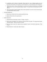
6. If adjustment must be made on thermostat, remove plug (30) in top of heating assembly and turn thermostat shaft clockwise with screwdriver to lower temperature or counterclockwise to raise temperature. 7. Adjustments must be made by starting below the cutoff point and raising the temperature in small steps (approximately 1/8 turn) until the proper setting is reached. The retort should not coast higher than 970°F (521°C). 8. After the thermostat is properly adjusted, allow the retort assembly to cool then remove the thermocouple, and reassemble the retort as normal. I. Pilot Light Replacement...
Open the catalog to page 16All RIGCHINA GROUP COMPANY catalogs and technical brochures
 12 Speed Viscometer
23 Pages
 6 Speed Viscometer
23 Pages
 Garrett Gas Train
28 Pages
 Core Saturator
4 Pages
 Mechanical Dynamometer 2016
3 Pages
 Deadline Anchors
11 Pages
 Weight Indicator systems
11 Pages
 PRESSURE GAUGE MODEL 8
5 Pages
 MUD PUMP PRESSURE GAUGES
19 Pages
 DRILLING INSTRUMENTATION
38 Pages


- Bourn And Koch oven
- Bourn And Koch dynamic mixer
- Bourn And Koch chamber oven
- Bourn And Koch measuring instrument
- Bourn And Koch electric oven
- Bourn And Koch heat treatment oven
- Bourn And Koch cooler
- Bourn And Koch batch mixer
- Bourn And Koch test bench
- Bourn And Koch pressure gauge
- Bourn And Koch calibrator
- Bourn And Koch solids analyzer
- Bourn And Koch liquid cooler
- Liquid homogenizer
- Bourn And Koch analog pressure gauge
- Laboratory shaker
- Stainless steel homogenizer
- Weighing terminal
- Laboratory kiln
- Real-time analyzer