Catalog excerpts

DRILLNG FLUID TESTING INSTRUMENTATION RheoADR Automated Digital Rheometer Automated Digital Rheometer Model NRC-130 Instruction Manual Email: service@rigchina.com SKYPE:RIGCHINA Website: http://www.rigchina.com Telephone: 0086-579-87537698 Fax: 0086-579-8753 696 Address: No.80-82, Qiude Road, West Cheng Industrial Estate, Yongkang city, Zhejiang Province, China,Postcode: 321300
Open the catalog to page 1
DRILLNG FLUID TESTING INSTRUMENTATION RheoVADR™ Rheometer ©2014 Rigchina Group Company All rights reserved. No part of this work covered by the copyright hereon may be reproduced or copied in any form or by any means (graphic, electronic, or mechanical) without first receiving the written permission of Rigchina Group Company
Open the catalog to page 2
DRILLNG FLUID TESTING INSTRUMENTATION RheoVADR™ Rheometer 1. Introduction The RheoADR™ is a direct-reading instrument for evaluating the rheological properties of fluids, Newtonian and non-Newtonian. The advantages of the RheoADR™ are its digital display, pre-programmed API tests, data recording feature, and speed range — 6 preset. This design includes a R1 Rotor Sleeve, B1 Bob, F1 Torsion Spring, and a stainless steel sample cup for testing according to American Petroleum Institute Recommended Practice for Field Testing Water Based Drilling Fluids, API RP 13B1/ISO 10414-1...
Open the catalog to page 3
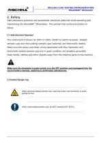
DRILLNG FLUID TESTING INSTRUMENTATION RheoVADR™ Rheometer 2. Safety Safe laboratory practices and procedures should be observed while operating and maintaining the RheoADR™ Rheometer. This section lists some precautions to follow. 2.1 Safe Electrical Operation This instrument is driven by 100V to 240V, 50/60 Hz electrical power. Heated sample cups and recirculating sample cups (optional) are electrically heated. Make sure the power and other wiring associated with this rheometer and electrically heated sample cups are in good condition and properly grounded. Keep hands, clothes and...
Open the catalog to page 4
DRILLNG FLUID TESTING INSTRUMENTATION RheoVADR™ Rheometer 3. Features and Specifications RheoADR™ Rheometer comes with the standard R1 rotor sleeve, B1 bob, F1 torsion spring, and a stainless steel sample cup. Its features include the following: Preprogrammed API tests— API drilling fluid and API cement Resistance Temperature Detector (RTD) for 0.5°F accuracy and Repeatability Secure fit, left-hand turn for rotor and right-hand turn for bob to help prevent disconnection when measuring high viscosity fluids LED display for high-contrast , making it easier to read LED-lighted sample...
Open the catalog to page 5
DRILLNG FLUID TESTING INSTRUMENTATION RheoVADR™ Rheometer Table 3-2 Rotor and Bob Dimensions Unit Cylinder Area (cm2) x Radius Table 3-3 Rotor-Bob Specifications ROTOR-BOB Rotor Radius, R0 (cm) Bob Radius, Ri (cm) Bob Height, L (cm) Shear Gap in Annulus (cm) Radii Ratio, Ri /R0 Maximum Use Temperature (oC) Table 3-4 Range of Environmental Conditions Maximum Altitude 41oF to 104oF (5oC to 40oC) 80% RH at 87.8oF (31oC) or Maximum Relative Humidity (RH) less 50% RH at 104oF (40oC) Temperature Range
Open the catalog to page 6
DRILLNG FLUID TESTING INSTRUMENTATION RheoVADR™ Rheometer 4 Installation The RheoADR™ Rheometer should be placed where there is easy access to the power cord plug for disconnection. Bob Removal and Installation To remove or install the bob, urn the bob counterclockwise (left) to remove it and clockwise (right) to install it (righthand-threads). Consideration should be given to the location where samples are prepared and equipment is cleaned when the test is completed. There should be sufficient storage area nearby for commonly used tools, as well as consumables.
Open the catalog to page 7
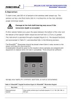
DRILLNG FLUID TESTING INSTRUMENTATION RheoVADR™ Rheometer To start a test, add 350 ml of sample to the stainless steel sample cup. The sample cup has a line that marks 350 ml. A scribed line on the rotor indicates proper immersion depth. Damage to the bob shaft bearing may occur if the immersion depth is exceeded. If other sample holders are used, the space between the bottom of the rotor and the bottom of the sample holder should be one-half inch (1.27cm) or greater. This instrument is operated through a keypad (Figure 5-1). The keypad functions are summarized in Table 5-1 and...
Open the catalog to page 8
DRILLNG FLUID TESTING INSTRUMENTATION RheoVADR™ Rheometer Plug the power supply into a 100V to 240V, 50/60 Hz power source. Connect the power supply to rear of the rheometer. Turn on the power switch. The LED backlight will show and the following screens will appear. After a few seconds, the machine enters the operating mode. The data display lists the speed (RPM), dial reading (DIAL), and the viscosity in centipoise (cP) in real-time. 5.2 Manual Operating Instructions Press white number keys to select preset speeds: 600, 300, 200, 100, 6, 3 Shutting down the rheometer Turn the...
Open the catalog to page 9
DRILLNG FLUID TESTING INSTRUMENTATION RheoVADR™ Rheometer 6.1 Deadweight or fluid calibration (Figure 6‐1). Shear Stress Measuring Range for RIGCHINA Viscometer Table 6-1 Torsion Spring Torsion Torsion Spring Constant, k1 Spring Assembly (with Dynes/cm/degre Factor f R1- B1 e deflection combination) Maximum Shear Stress with B1 Bob (dyne/cm2) Dial Range Dial Range Table 6-3 Shear Rate Measuring Range for Viscometers Rate of Revolution of Outer Cylinder, N (rpm) Shear Rate Range (sec-1), = k3N Rotor-Bob Combinations R1 B1
Open the catalog to page 10
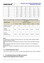
DRILLNG FLUID TESTING INSTRUMENTATION RheoVADR™ Rheometer Table 6-4 Viscosity Range in Centipoise for RIGCHINA Direct Indicating Viscometers All Models, 600 rpm max Minimum Viscosity (2) Notes: 1.Computed for standard Torsion Spring (F1). For other torsion springs multiply viscosity range by f factor. 2.Minimum viscosity is computed for minimum shear stress and maximum shear rate. 3.For practical purposes the minimum viscosity is limited to 0.5 cP because of Taylor Vortices. 4.Maximum viscosity is computed for maximum shear stress and minimum shear rate. 6.2 Fluid Calibration...
Open the catalog to page 11All RIGCHINA GROUP COMPANY catalogs and technical brochures
-
12 Speed Viscometer
23 Pages
-
6 Speed Viscometer
23 Pages
-
Garrett Gas Train
28 Pages
-
Core Saturator
4 Pages
-
Mechanical Dynamometer 2016
3 Pages
-
Deadline Anchors
11 Pages
-
Weight Indicator systems
11 Pages
-
PRESSURE GAUGE MODEL 8
5 Pages
-
MUD PUMP PRESSURE GAUGES
19 Pages
-
DRILLING INSTRUMENTATION
38 Pages
-
Oil and Water Retort Kit
19 Pages


